Other Parts Discussed in Thread: MSP430F5438A, SMARTRFTRXEBK
Tool/software:
Hi everyone,
I am working on CC125 using pic32cm5164ls60100 I need basic example code for transmitting data through cc125
Thanks.
This thread has been locked.
If you have a related question, please click the "Ask a related question" button in the top right corner. The newly created question will be automatically linked to this question.
Tool/software:
Hi everyone,
I am working on CC125 using pic32cm5164ls60100 I need basic example code for transmitting data through cc125
Thanks.
Hi Siri,
Thanks for reply
SWRC253 Code example or demo | TI.com
I downloaded the project from above link and when I was importing the project it was not happening in CCS
Can you tell me the steps to only transmit data through CC1125 using SPI without using any interrupt.
I am new to RF communication.
Best regard
Sudhir
you can look at the file CC112x_easy_link_tx.c that show a very simple example on how to transmit a packet.
The necessary steps you need to implement are the following:
Init you MCU
Init the radio with the SPI registers exported from SmartRF Studio (settings found in the cc112x_easy_link_reg_config.h)
Write the data to your TX FIFO
Strobe STX.
The SPI functions are found here:
\source\components\targets\trxeb_msp430f5438a
and must be ported to your MCU
Siri
Hi Siri,
Thanks for reply,
i follow your instruction but my cc1125 does not generate interrupt and stuck at while(packetSemaphore != ISR_ACTION_REQUIRED);
i also checked Oscilloscope GPIO 2 IS continue 3.3V
Right now i am using SMARTRFTRXEBK and i have 2 SMARTRFTRXEBK.
But one of my friend give one example code by using that code i am getting some result.
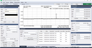
This is the result continuously i get on spectrum analyzer and i don't know this is data or something else .

but the problem is when i try to receive this transmitted data on another SMARTRFTRXEBK using smart studio RF i did not get any result.
but when i used SMARTRFTRXEBK using smart RF studio for transmitting and receiving both i am able to receive and send but with code i am getting signal on spectrum analyzer.
BELOW is my code
cc112xSpiReadReg(CC112X_PARTNUMBER, &Device_id, 1); //Read Devcie ID CC1125 = 0x58
if(Device_id == 0x58)
{
P4OUT &= ~BIT0; // Led1 ON
Crystal_freq.ver = 0x01;
}
Crystal_freq.id = Device_id;
// trxDetectRfCrystalFrequency(&Crystal_freq);
trxSpiCmdStrobe(CC112X_SRES); // RESET Radio
registerConfig();
unsigned char writeByte=0x06;
// manualCalibration();
cc112xSpiWriteReg(CC112X_IOCFG2, &writeByte, 1);
cc112xSpiReadReg( CC112X_IOCFG2,®_red,1);
//-------------------------- Rx
// trxSpiCmdStrobe(CC112X_SIDLE); // Ideal
cc112xSpiWriteReg(CC112X_IOCFG3,&gpioConfigSlave[0],4);
Delay(60000);
manualCalibration();
Delay(60000);
calibrateRCOsc();
Delay(60000);
trxSpiCmdStrobe(CC112X_SRX);
cc112xSpiWriteReg(CC112X_PKT_CFG0, 0x40, 1); // PKT_CFG = Infinit Packet mod
cc112xSpiWriteReg(CC112X_PKT_LEN, 0x00, 1); // PKT_Lenght 256
Tx_buff[0] =00;
for(i=1; i<(Buff_Size+1); i++)
{
Tx_buff[i] = 'A';
}
trxSpiCmdStrobe(CC112X_SFTX); // Flush Tx buffer
/
cc112xSpiWriteTxFifo(Tx_buff, (Buff_Size+1));
// Strobe TX to send packet
trxSpiCmdStrobe(CC112X_STX);
Tx_buff[0] =Buff_Size+1;
for(i=1; i<(Buff_Size+1); i++)
{
Tx_buff[i] = 'B';
}
trxSpiCmdStrobe(CC112X_SFTX); // Flush Tx buffer
Delay(60000);//
cc112xSpiWriteTxFifo(Tx_buff, (Buff_Size+1));
trxSpiCmdStrobe(CC112X_SFTX); // Flush Tx buffer
cc112xSpiWriteReg(CC112X_PKT_CFG0, 0x20, 1); // PKT_CFG = Infinit Packet mod
cc112xSpiWriteReg(CC112X_PKT_LEN, 0x30, 1); // PKT_Lenght 256
Tx_buff[0] =48;
for(i=1; i<49; i++)
{
Tx_buff[i] = 'C';
}
trxSpiCmdStrobe(CC112X_SFTX); // Flush Tx buffer
Delay(60000);//
cc112xSpiWriteTxFifo(Tx_buff, 49);
trxSpiCmdStrobe(CC112X_SFTX); // Flush Tx buffer
trxSpiCmdStrobe(CC112X_SIDLE);
Best regard
Mayank
Please follow my advice as to what the code needs to do.
Since you are using our EMs we know that the HW is good, so the problem must be related to SW.
I do not understand at all what you are trying to do with the posted code, mixing infinite packet length mode and varialbe packet length mode etc, and I do not know what register settings you are using.
You should test some simple code like this:
Use the following settings from SmartRF Studio:
// Address Config = No address check
// Bit Rate = 1.2
// Carrier Frequency = 869.224854
// Deviation = 3.995895
// Device Address = 0
// Manchester Enable = false
// Modulation Format = 2-GFSK
// PA Ramping = true
// Packet Bit Length = 0
// Packet Length = 255
// Packet Length Mode = Variable
// Performance Mode = High Performance
// RX Filter BW = 15.625000
// Symbol rate = 1.2
// TX Power = 15
// Whitening = false

static const registerSetting_t preferredSettings[]=
{
  {CC1125_IOCFG3,            0xB0},
  {CC1125_IOCFG2,            0x06},
  {CC1125_IOCFG1,            0xB0},
  {CC1125_IOCFG0,            0x40},
  {CC1125_SYNC_CFG1,         0x08},
  {CC1125_DEVIATION_M,       0xA3},
  {CC1125_MODCFG_DEV_E,      0x0A},
  {CC1125_DCFILT_CFG,        0x1C},
  {CC1125_FREQ_IF_CFG,       0x33},
  {CC1125_IQIC,              0xC6},
  {CC1125_CHAN_BW,           0x10},
  {CC1125_MDMCFG0,           0x05},
  {CC1125_SYMBOL_RATE2,      0x3F},
  {CC1125_SYMBOL_RATE1,      0x75},
  {CC1125_SYMBOL_RATE0,      0x10},
  {CC1125_AGC_REF,           0x20},
  {CC1125_AGC_CS_THR,        0x19},
  {CC1125_AGC_CFG1,          0xA9},
  {CC1125_AGC_CFG0,          0xCF},
  {CC1125_FIFO_CFG,          0x00},
  {CC1125_FS_CFG,            0x12},
  {CC1125_PKT_CFG0,          0x20},
  {CC1125_PKT_LEN,           0xFF},
  {CC1125_IF_MIX_CFG,        0x00},
  {CC1125_FREQOFF_CFG,       0x22},
  {CC1125_FREQ2,             0x56},
  {CC1125_FREQ1,             0xEC},
  {CC1125_FREQ0,             0x28},
  {CC1125_IF_ADC0,           0x05},
  {CC1125_FS_DIG1,           0x00},
  {CC1125_FS_DIG0,           0x5F},
  {CC1125_FS_CAL0,           0x0E},
  {CC1125_FS_DIVTWO,         0x03},
  {CC1125_FS_DSM0,           0x33},
  {CC1125_FS_DVC0,           0x17},
  {CC1125_FS_PFD,            0x50},
  {CC1125_FS_PRE,            0x6E},
  {CC1125_FS_REG_DIV_CML,    0x14},
  {CC1125_FS_SPARE,          0xAC},
  {CC1125_XOSC5,             0x0E},
  {CC1125_XOSC3,             0xC7},
  {CC1125_XOSC1,             0x07},
};
#define PKTLEN	5

uint8 Tx_buff[PKTLEN + 1] = {0};
uint8 Rx_buff[PKTLEN + 1 + 2] = {0}; // Need to have room for length byte and 2 status bytes

trxSpiCmdStrobe(CC112X_SRES); // RESET Radio

registerConfig();

// if PARTVERSION is 0x21, do manual calibration (if this is the case, SETTLING_CFG should be set to 0x03 instead of 0x0B)
// manualCalibration();

// Implement packet length filtering to avoid overflow
// PKTLEN must no be larger than 128 - 3 = 125  to make sure that the comeplete payload + length byte + status bytes
// ha ve room in the FIFO
writeByte = PKTLEN;
cc112xSpiWriteReg(CC112X_PKT_LEN, &writeByte, 1);

//--------------------------------------------------------------
// TX:
//--------------------------------------------------------------
Tx_buff[0] = PKTLEN; // Length byte

for(i = 1; i < (PKTLEN + 1); i++)
{
    Tx_buff[i] = 'A'; // Payload consiste of 0xAAAAAAAAAA
}

// Write the packet to the TX FIFO
cc112xSpiWriteTxFifo(Tx_buff, sizeof(Tx_buff));

// Strobe TX to send packet
trxSpiCmdStrobe(CC112X_STX);

// Wait for falling edge of GDO2
//--------------------------------------------------------------

//--------------------------------------------------------------
// RX:
//--------------------------------------------------------------
trxSpiCmdStrobe(CC112X_SRX);

// Wait for falling edge of GDO2

// Read the RX FIFO when a packet has been received
Siri