This thread has been locked.

If you have a related question, please click the "Ask a related question" button in the top right corner. The newly created question will be automatically linked to this question.

CC1125: Issues faced with CC1125 reception

Part Number: CC1125
Other Parts Discussed in Thread: , , , CC1120EMK-420-470

Tool/software:

I am currently working with CC1125 transceiver chip for my project. The chip is matched for UHF frequency band and I wanted to calibrate the registers of the chip through my microcntroller. I wanted to check the transmission as well as reception. The transmission is working perfectly. We were able to send the data with 465 MHz through our actual board and receive it in the CC1125 Eval board through smart RF. Next we needed to do receiver sensitivity test. For that, initially, I tried sending the data through CC1125 EVM with 465 MHz and 15 dbm transmit power and receive it through the CC1125 chip which is connected in my actaul board. It is working fine. But, when I tested the reception for low transmit power, by keeping attenuators in between, I am not able to receive the packets with power less than -30 db. When I checked the marcstate, it is showing settling state. Why is this happening? Is it due to the matching cirucit issue in my board or is it because the EVM is matched to 868 MHz or should I need to take care of any register configurations so as to increase the sensitivity of the chip?

Any particular register involved in increasing the sensitivity of the chip? Right now, I am following the smartRF log.

  • Hi,

    A couple of points:

    • Please can you clarify: what hardware are you using for this, the CC1125DK, the BOOSTXL-CC1125, or something else (custom HW)?
    • What is your setup - you mention using attenuators (which makes sense) so I assume these are conducted measurements, but when you mention "with power less than -30 dbm" are you referring to the RSSI reading or the transmit output power setting (I would think the latter)? What is the RSSI reading if so?
    • If the matching network is for 868/915 MHz then this will impact the performance quite significantly, particularly in RX because the discrete LC-balun has a limited bandwidth and is not tuned for 465 MHz performance. We would strongly recommend mounting the correct BOM if this is the case.

    Regards,

    Zack

    • We are using CC1125DK for testing and the software used is smartRF.
    • The test setup is conduction mode. So, what we are doing is: From CC1125DK we are sending 450 MHz 4FSK Modulated signal at 0 dbm Tx power at 9.6 kbps data rate. From the HDK, we are taking RF cables and connecting some 20 db attenuators. This data is going to the RF frone end, from where additional 15 dbm loss of data will be there. This data is reaching the CC1125 chip. Since, the CC1125 HDK is not matched to 450 MHz, we are getting some 5 dbm loss of data from the HDK itself. So the total Tx power will be -40 dbm, which is reaching the CC1125. With this setup, we ae not receiving the packets.
    • Can you please explain what is LC-balun?
  • We are using CC1125DK for testing and the software used is smartRF.

    The first step for resolving this should be using the correct BOM for 420-470 MHz operation.

    Can you please explain what is LC-balun?

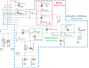
    Of course - a balun converts a BALanced input to an UNbalanced output and vice-versa. The LC- part of the name in this case is because it is implemented using lumped LC components (rather than some of the alternative types possible). The LNA has a balanced input (LNA_N and LNA_P) but the received signal at the antenna is single-ended (unbalanced), so a balun is required for correct LNA operation.

    LC baluns in the topology used have a limited bandwidth and the BOM on the CC1125DK is for 868/915 MHz operation. Using the device outside of the frequency range is not expected to work correctly (if at all).

    Additionally, there are notch filters inthe TX path which are also specifically tuned for 868/915 MHz operation and will not resonate at 420-470 MHz, further degrading the performance.

    You have two alternatives to use the correct BOM:

    1. Mount the 420-470 MHz BOM on the CC1125DK. The relevant reference designs are:
      1. CC112xEM_420_470 (SWRC221): https://www.ti.com/lit/zip/swrc221 - this is the correct BOM for 420-470 MHz operation.
      2. CC1125EM-868-915-RD (SWRR102): https://www.ti.com/lit/zip/swrr102 - this is the BOM originally mounted on the CC1125DK (for reference).

    2. Use the CC1120EMK-420-470: https://www.ti.com/tool/CC1120EMK-420-470 and mount a CC1125 and 40 MHz XTAL.

    Option 1 is probably the easiest (and cheapest).

    Note you need to change the BOM of the entire RF path (and VDD bias), which you will see differs for 868-915 MHz and 420-470 MHz operation as the RF matching is interdependent. 

    Regards,

    Zack