This thread has been locked.

If you have a related question, please click the "Ask a related question" button in the top right corner. The newly created question will be automatically linked to this question.

CC1190: Transmission line length on RX vs TX side

Part Number: CC1190


Tool/software:

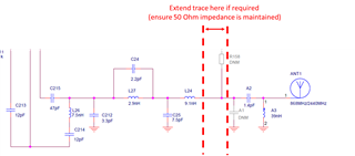
If we have a rectangular, listening and retransmitting PCB with receiving antenna connector along one short end and a transmitting chip antenna at the other, where should the CC1190 optimally sit along the length of PCB? Chip antenna manufacturer wants a short transmission line between PA and antenna, while we're concerned of the receiving side being more susceptible to noise and interference if there's a long trace on the reception side.

  • Hi,

    The "rule of thumb" is to try and keep the length of the trace less than 1/10 of the wavelength of the frequency of interest to avoid transmission line propagation effects.

    Therefore, it is unlikely to affect the RX performance with a short transmission line between the PA antenna if the trace is shorter than this, and may even be recommended so that an antenna matching network (or at least the component footprints for one) can be included.

    It is a good idea to check that the transmission line has a 50 Ohm impedance to avoid impedance mismatch using simple tools such as:

    Regards,

    Zack

  • Hi, PCB length is 10cm and our wavelength is 30cm, so keeping trace length below 1/10 is impossible, it's just a matter of whether to have it on TX or RX side (or both) of CC1190. Are you suggesting that it's better to have that length mostly on the RX side, and there should be no adverse effects on RX quality?

  •  it's just a matter of whether to have it on TX or RX side (or both) of CC1190

    Are you referring to the RF paths between the device and the CC1190? I don't have all of the context for this design, so I'm not sure how making only one of the paths (RX or TX) would be possible.

    The main concern would be ensuring that the RF matching was not affected (so accounting for any change in the input impedance presented to the LNA). Therefore, it would become even more important to check that the trace impedance of this longer trace is maintained, i.e. ensuring that it is 50 Ohms. 

    The RF path from the CC1190 to the antenna is shared between RX and TX operation. What would recommend is to extend the length of the trace after the CC1190 matching/filtering network (to the antenna) as this would minimise the effect on the RF matching. Keeping the footprint for the antenna matching network (Pi-network) would minimise risk so that you can adjust the antenna matching if there are any issues.  

    Regards,

    Zack

  • Hi, apologies, should have started with a (crude) schematic picture since we don't have 100% the same configuration as in the eval board. The radio path is split between RX from external antenna connector into LNA and TX from PA to a chip antenna, with roughly 100mm between said connector and antenna. The splitting I already confirmed with TI months ago so that's ok. 

    The question in all simplicity boils down to are we ok with having all of the matching and filtering components bunched up right between CC1190 and antenna like on the eval board (length at B = 0), and then having a long honking asymmetric stripline running from the LNA down to the antenna connector (A = 80ish mm)?

    Happy to share a draft layout privately if that helps.
    -Jussi

  • Hi Jussi,

    The image is corrupted in your reply but I've contacted you via PM so you can resend it there.

    Ultimately, it's probably still better to keep the matching/filtering section close together (it's a compromise either way). As mentioned above, keeping the trace impedance to the antenna 50 Ohms will become more important.

    I will mark the thread as resolved due to moving to PM (so you can share your draft layout non-publicly).

    Regards,
    Zack