Other Parts Discussed in Thread: SYSCONFIG, CSD, SYSBIOS
Tool/software:
We designed a new IoT device and are measuring its power consumption to optimize energy efficiency, particularly in sleep mode.
In our measurements, we used three identical sensors with the same hardware and firmware. However, each device exhibits unique and varying power consumption in sleep mode:
- Device_1: 2.26 µA
- Device_2: 132 µA
- Device_3: 94.9 µA
Based on our calculations, we expected the sleep mode power consumption to be between 12-15 µA.
To investigate whether the issue is related to our firmware, we examined the efficiency of GPIO usage in relation to our hardware design. To test this, we flashed our IoT device with a basic empty example project for the CC1312R, configured the GPIO pins using SysConfig, and repeated the measurements. However, we still observed the same power consumption values as you seen from the below picutre.
As shown in the image below, there are also maximum peak measurements. I suspect the issue might be related to our O₂ sensor (Luminox); however, we are not supplying power to it via GPIOs.
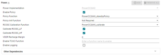
also here is my sysconfig as text form:
/**
* These arguments were used when this file was generated. They will be automatically applied on subsequent loads
* via the GUI or CLI. Run CLI with '--help' for additional information on how to override these arguments.
* @cliArgs --board "/ti/boards/CC1312R1_LAUNCHXL" --rtos "tirtos7" --product "simplelink_cc13xx_cc26xx_sdk@6.41.00.17"
* @versions {"tool":"1.15.0+2826"}
*/
/**
* Import the modules used in this configuration.
*/
const ADC = scripting.addModule("/ti/drivers/ADC", {}, false);
const ADC1 = ADC.addInstance();
const GPIO = scripting.addModule("/ti/drivers/GPIO");
const GPIO2 = GPIO.addInstance();
const GPIO3 = GPIO.addInstance();
const GPIO4 = GPIO.addInstance();
const GPIO5 = GPIO.addInstance();
const GPIO6 = GPIO.addInstance();
const GPIO7 = GPIO.addInstance();
const GPIO8 = GPIO.addInstance();
const GPIO9 = GPIO.addInstance();
const GPIO10 = GPIO.addInstance();
const I2C = scripting.addModule("/ti/drivers/I2C", {}, false);
const I2C1 = I2C.addInstance();
const Power = scripting.addModule("/ti/drivers/Power");
const UART2 = scripting.addModule("/ti/drivers/UART2", {}, false);
const UART21 = UART2.addInstance();
const UART22 = UART2.addInstance();
const Watchdog = scripting.addModule("/ti/drivers/Watchdog", {}, false);
const Watchdog1 = Watchdog.addInstance();
const Button = scripting.addModule("/ti/drivers/apps/Button", {}, false);
const Button1 = Button.addInstance();
const LED = scripting.addModule("/ti/drivers/apps/LED", {}, false);
const LED1 = LED.addInstance();
const LED2 = LED.addInstance();
const LED3 = LED.addInstance();
const Settings = scripting.addModule("/ti/posix/tirtos/Settings");
const BIOS = scripting.addModule("/ti/sysbios/BIOS");
const Event = scripting.addModule("/ti/sysbios/knl/Event");
const Idle = scripting.addModule("/ti/sysbios/knl/Idle", {}, false);
const Idle2 = Idle.addInstance();
const Mailbox = scripting.addModule("/ti/sysbios/knl/Mailbox");
const Error = scripting.addModule("/ti/sysbios/runtime/Error");
const SysCallback = scripting.addModule("/ti/sysbios/runtime/SysCallback");
const Timestamp = scripting.addModule("/ti/sysbios/runtime/Timestamp");
/**
* Write custom configuration values to the imported modules.
*/
ADC1.$name = "CONFIG_BATTERY_ADC";
ADC1.adc.adcPin.$assign = "boosterpack.2";
ADC1.adcPinInstance.mode = "Output";
ADC1.adcPinInstance.initialOutputState = "High";
GPIO2.$name = "CONFIG_CO2_PWR_GPIO";
GPIO2.pull = "Pull Down";
GPIO2.mode = "Output";
GPIO2.outputStrength = "Low";
GPIO2.gpioPin.$assign = "boosterpack.11";
GPIO3.$name = "CONFIG_5V_GPIO";
GPIO3.pull = "Pull Down";
GPIO3.mode = "Output";
GPIO3.outputStrength = "Low";
GPIO3.gpioPin.$assign = "boosterpack.8";
GPIO4.$name = "CONFIG_O2_PWR_GPIO";
GPIO4.outputStrength = "Low";
GPIO4.pull = "Pull Down";
GPIO4.mode = "Output";
GPIO4.gpioPin.$assign = "boosterpack.38";
scripting.suppress("Connected to hardware,@@@.+?@@@ is connected to MX25R8035F SPI Flash Chip Select on the CC1312R1 LaunchPad\\. Consider selecting it in 'use hardware' above\\. @@@.+?@@@", GPIO4, "gpioPin");
GPIO5.$name = "CONFIG_FE_CPS_GPIO";
GPIO5.mode = "Output";
GPIO5.outputStrength = "High";
GPIO5.gpioPin.$assign = "boosterpack.39";
scripting.suppress("Connected to hardware,@@@.+?@@@ is connected to LaunchPad LED Red on the CC1312R1 LaunchPad\\. Consider selecting it in 'use hardware' above\\. @@@.+?@@@", GPIO5, "gpioPin");
GPIO6.$name = "CONFIG_FE_CTX_GPIO";
GPIO6.mode = "Output";
GPIO6.outputStrength = "High";
GPIO6.gpioPin.$assign = "boosterpack.10";
GPIO7.$name = "CONFIG_FE_CSD_GPIO";
GPIO7.mode = "Output";
GPIO7.gpioPin.$assign = "boosterpack.40";
scripting.suppress("Connected to hardware,@@@.+?@@@ is connected to LaunchPad LED Green on the CC1312R1 LaunchPad\\. Consider selecting it in 'use hardware' above\\. @@@.+?@@@", GPIO7, "gpioPin");
GPIO8.$name = "CONFIG_HUM_PWR_GPIO";
GPIO8.initialOutputState = "High";
GPIO8.pull = "Pull Down";
GPIO8.mode = "Output";
GPIO8.outputStrength = "Low";
GPIO8.gpioPin.$assign = "boosterpack.15";
scripting.suppress("Connected to hardware,@@@.+?@@@ is connected to LaunchPad SPI Bus on the CC1312R1 LaunchPad\\. Consider selecting it in 'use hardware' above\\. @@@.+?@@@", GPIO8, "gpioPin");
GPIO9.$name = "CONFIG_HUM_RST_GPIO";
GPIO9.initialOutputState = "High";
GPIO9.pull = "Pull Down";
GPIO9.mode = "Output";
GPIO9.gpioPin.$assign = "boosterpack.14";
scripting.suppress("Connected to hardware,@@@.+?@@@ is connected to LaunchPad SPI Bus on the CC1312R1 LaunchPad\\. Consider selecting it in 'use hardware' above\\. @@@.+?@@@", GPIO9, "gpioPin");
GPIO10.$name = "CONFIG_HUM_ALERT_GPIO";
GPIO10.initialOutputState = "High";
GPIO10.gpioPin.$assign = "boosterpack.19";
I2C1.$name = "CONFIG_I2C_0";
I2C1.i2c.sdaPin.$assign = "boosterpack.36";
I2C1.i2c.sclPin.$assign = "boosterpack.37";
I2C1.sdaPinInstance.mode = "Output";
I2C1.sdaPinInstance.initialOutputState = "High";
I2C1.sclPinInstance.mode = "Output";
I2C1.sclPinInstance.initialOutputState = "High";
const CCFG = scripting.addModule("/ti/devices/CCFG", {}, false);
CCFG.ccfgTemplate.$name = "ti_devices_CCFG_CCFGCC26XXTemplate0";
UART21.$name = "CONFIG_UART2_3";
UART21.uart.txPin.$assign = "boosterpack.13";
UART21.uart.rxPin.$assign = "boosterpack.12";
UART21.txPinInstance.initialOutputState = "Low";
UART21.rxPinInstance.pull = "None";
scripting.suppress("Connected to hardware,@@@.+?@@@ is connected to LaunchPad Button BTN-1 \\(Left\\) on the CC1312R1 LaunchPad\\. Consider selecting it in 'use hardware' above\\. @@@.+?@@@", UART21.uart, "txPin");
scripting.suppress("Connected to hardware,@@@.+?@@@ is connected to LaunchPad Button BTN-2 \\(Right\\) on the CC1312R1 LaunchPad\\. Consider selecting it in 'use hardware' above\\. @@@.+?@@@", UART21.uart, "rxPin");
UART22.$name = "CONFIG_UART2_2";
UART22.uart.txPin.$assign = "boosterpack.7";
UART22.uart.rxPin.$assign = "boosterpack.18";
UART22.txPinInstance.initialOutputState = "Low";
UART22.rxPinInstance.pull = "None";
scripting.suppress("Connected to hardware,@@@.+?@@@ is connected to LaunchPad SPI Bus on the CC1312R1 LaunchPad\\. Consider selecting it in 'use hardware' above\\. @@@.+?@@@", UART22.uart, "txPin");
scripting.suppress("Connected to hardware,@@@.+?@@@ is connected to LaunchPad SPI Bus Chip Select on the CC1312R1 LaunchPad\\. Consider selecting it in 'use hardware' above\\. @@@.+?@@@", UART22.uart, "rxPin");
Watchdog1.$name = "CONFIG_WATCHDOG_0";
Button1.$name = "CONFIG_BUTTON_BD";
Button1.button.$assign = "boosterpack.6";
Button1.gpioPin.initialOutputState = "High";
LED1.$name = "CONFIG_LED_RED";
LED1.ledPin.$assign = "boosterpack.23";
LED1.gpioPin.initialOutputState = "High";
LED2.$name = "CONFIG_LED_BLUE";
LED2.ledPin.$assign = "boosterpack.24";
LED2.gpioPin.initialOutputState = "High";
LED3.$name = "CONFIG_LED_GREEN";
LED3.ledPin.$assign = "boosterpack.25";
LED3.gpioPin.initialOutputState = "High";
BIOS.assertsEnabled = false;
BIOS.heapBaseAddr = "__primary_heap_start__";
BIOS.heapEndAddr = "__primary_heap_end__";
const Hwi = scripting.addModule("/ti/sysbios/family/arm/m3/Hwi", {}, false);
Hwi.enableException = false;
const Clock = scripting.addModule("/ti/sysbios/knl/Clock", {}, false);
Clock.tickPeriod = 10;
const Timer = scripting.addModule("/ti/sysbios/family/arm/cc26xx/Timer", {}, false);
Idle2.$name = "powerIdle";
Idle2.idleFxn = "Power_idleFunc";
const Semaphore = scripting.addModule("/ti/sysbios/knl/Semaphore", {}, false);
Semaphore.supportsPriority = false;
const Swi = scripting.addModule("/ti/sysbios/knl/Swi", {}, false);
Swi.numPriorities = 6;
const Task = scripting.addModule("/ti/sysbios/knl/Task", {}, false);
Task.checkStackFlag = false;
Task.defaultStackSize = 512;
Task.idleTaskStackSize = 512;
Task.numPriorities = 6;
Error.policy = "Error_SPIN";
Error.printDetails = false;
const System = scripting.addModule("/ti/sysbios/runtime/System", {}, false);
System.abortFxn = "System_abortSpin";
System.exitFxn = "System_exitSpin";
System.extendedFormats = "%f";
System.supportModule = "SysCallback";
/**
* Pinmux solution for unlocked pins/peripherals. This ensures that minor changes to the automatic solver in a future
* version of the tool will not impact the pinmux you originally saw. These lines can be completely deleted in order to
* re-solve from scratch.
*/
ADC1.adc.$suggestSolution = "ADC0";
I2C1.i2c.$suggestSolution = "I2C0";
UART21.uart.$suggestSolution = "UART1";
UART22.uart.$suggestSolution = "UART0";
Watchdog1.watchdog.$suggestSolution = "WDT0";
Timer.rtc.$suggestSolution = "RTC0";