This thread has been locked.

If you have a related question, please click the "Ask a related question" button in the top right corner. The newly created question will be automatically linked to this question.

CC1311P3: Need input on RF calibration as the RF performance is not meeting the expected results

Part Number: CC1311P3

Tool/software:

Hello,

We are working with the CC1311P3 RF IC for our reference design. We are looking for detailed information on its RF calibration procedure.

After reviewing the datasheet and technical documentation, we found that only RTC reference clock calibration is mentioned. However, we could not find any details regarding other RF-related calibrations, such as:

1)Frequency Calibration – Ensuring accurate carrier frequency output. We see a drift of 6KHz in the RF output 
2)TX Power Calibration – Verifying and tuning transmitted power levels.
3)RX Sensitivity Calibration – Optimizing receiver performance for weak signals.
4)Impedance Matching Calibration – Adjusting the RF matching network for minimal losses.


Additionally, we are facing an issue with harmonics in the transmitted signal. we need to check whether any calibration or tuning process can help reduce harmonic levels and improve spectral purity.
Are there any recommended steps, filtering techniques, or register settings to mitigate harmonics on the CC1311P3?

Could you please confirm if these calibrations are handled automatically by the RF core firmware, or do they require manual intervention? If manual calibration is needed, are there any specific registers, tools, or recommended procedures available?

Additionally, does SmartRF Studio provide any built-in calibration assistance, or should we rely on external test equipment for these adjustments?

Any guidance, documentation, or example procedures would be greatly appreciated.

Thanks!

  • Hi,

    As an initial step, please can you share more details about the high harmonics issue?

    Specifically:

    • Exactly what is failing.
    • Your test setup.
    • Conducted measurements (ideally spectrum analyser screengrabs).
    • The exact SmartRF Studio settings used.

    This is typically a HW issue as it is mainly affected by the external RF matching network - it isn't something that can be calibrated (apart from the PA table settings which typically should not be changed from the default settings).

    If we cannot rule out the root cause from this then we would recommend that you submit your schematic and layout for a review using Sub-1 GHz Design Review Submission: https://www.ti.com/tool/SIMPLELINK-SUB1GHZ-DESIGN-REVIEWS

    Regards,

    Zack

  • Hi Zack, 

    Thanks for reverting back!

    Please find the attachments for the following

    1. Spectrum charts showing multiple harmonics and drift in center frequency

    2. RF configuration file used from code composer studio

    3. The matching network used in our design

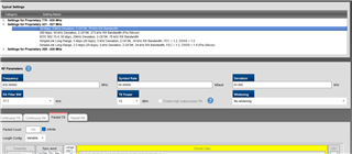
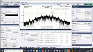
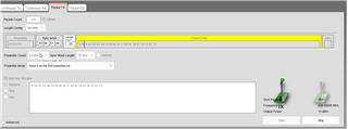
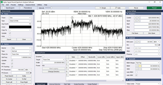
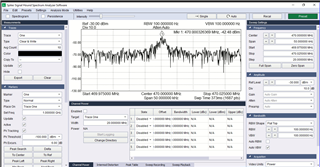
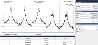
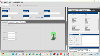
     (At higher TX power, multiple harmonics were observed as attached here and central peak is not clearly visible)

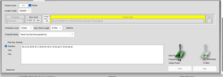
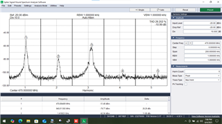
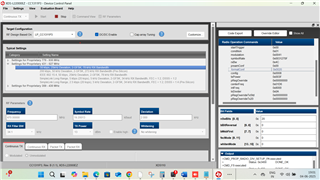
      (At lower TX power, the peak power is observed with a shift of 6KHz for 435MHz configured center frequency)

    /**
     * These arguments were used when this file was generated. They will be automatically applied on subsequent loads
     * via the GUI or CLI. Run CLI with '--help' for additional information on how to override these arguments.
     * @cliArgs --device "CC1311P3RGZ" --package "RGZ" --part "Default" --rtos "freertos" --product "simplelink_cc13xx_cc26xx_sdk@7.41.00.17"
     * @versions {"tool":"1.18.1+3343"}
     */
    
    /**
     * Import the modules used in this configuration.
     */
    const FreeRTOS = scripting.addModule("/freertos/FreeRTOS");
    const CCFG     = scripting.addModule("/ti/devices/CCFG");
    const custom   = scripting.addModule("/ti/devices/radioconfig/custom");
    const rfdesign = scripting.addModule("/ti/devices/radioconfig/rfdesign");
    const GPIO     = scripting.addModule("/ti/drivers/GPIO");
    const GPIO1    = GPIO.addInstance();
    const GPIO2    = GPIO.addInstance();
    const GPIO3    = GPIO.addInstance();
    const GPIO4    = GPIO.addInstance();
    const GPIO5    = GPIO.addInstance();
    const GPIO6    = GPIO.addInstance();
    const GPIO7    = GPIO.addInstance();
    const GPIO8    = GPIO.addInstance();
    const GPIO9    = GPIO.addInstance();
    const GPIO10   = GPIO.addInstance();
    const GPIO11   = GPIO.addInstance();
    const GPIO12   = GPIO.addInstance();
    const GPIO13   = GPIO.addInstance();
    const GPIO14   = GPIO.addInstance();
    const GPIO15   = GPIO.addInstance();
    const RF       = scripting.addModule("/ti/drivers/RF");
    const UART2    = scripting.addModule("/ti/drivers/UART2");
    const UART21   = UART2.addInstance();
    const Settings = scripting.addModule("/ti/posix/freertos/Settings");
    
    /**
     * Write custom configuration values to the imported modules.
     */
    CCFG.xoscCapArray               = true;
    CCFG.xoscCapArrayDelta          = 0xC1;
    CCFG.dioBootloaderBackdoor      = 15;
    CCFG.levelBootloaderBackdoor    = "Active low";
    CCFG.xoscSinglePointCalibration = "30";
    CCFG.forceVddr                  = true;
    CCFG.enableBootloader           = true;
    CCFG.tcxoType                   = "Clipped-sine Type";
    CCFG.enableDCDC                 = false;
    CCFG.ccfgTemplate.$name         = "ti_devices_CCFG_CCFGCC26XXTemplate0";
    
    custom.prop4                                       = ["custom433"];
    custom.radioConfigcustom433.$name                  = "ti_devices_radioconfig_settings_prop0";
    custom.radioConfigcustom433.preambleCount          = "1 Bit";
    custom.radioConfigcustom433.carrierFrequency       = 434.0000;
    custom.radioConfigcustom433.codeExportConfig.$name = "ti_devices_radioconfig_code_export_param0";
    
    rfdesign.fbSub1g = "fb433";
    
    GPIO1.$name              = "CONFIG_GPIO_SPDT_CTRL_V1";
    GPIO1.mode               = "Output";
    GPIO1.outputStrength     = "Low";
    GPIO1.initialOutputState = "High";
    GPIO1.gpioPin.$assign    = "DIO_28";
    
    GPIO2.$name              = "CONFIG_GPIO_SPDT1_CTRL";
    GPIO2.mode               = "Output";
    GPIO2.initialOutputState = "High";
    GPIO2.gpioPin.$assign    = "DIO_27";
    
    GPIO3.$name              = "CONFIG_GPIO_LOGIC_CTRL1";
    GPIO3.mode               = "Output";
    GPIO3.initialOutputState = "High";
    GPIO3.gpioPin.$assign    = "DIO_14";
    
    GPIO4.$name           = "CONFIG_GPIO_SPDT_CTRL_V2";
    GPIO4.mode            = "Output";
    GPIO4.outputStrength  = "Low";
    GPIO4.gpioPin.$assign = "DIO_29";
    
    GPIO5.$name           = "CONFIG_GPIO_C16_ATT1";
    GPIO5.mode            = "Output";
    GPIO5.outputStrength  = "High";
    GPIO5.gpioPin.$assign = "DIO_26";
    
    GPIO6.$name           = "CONFIG_GPIO_C8_ATT1";
    GPIO6.mode            = "Output";
    GPIO6.outputStrength  = "High";
    GPIO6.gpioPin.$assign = "DIO_7";
    
    GPIO7.$name           = "CONFIG_GPIO_C4_ATT1";
    GPIO7.mode            = "Output";
    GPIO7.outputStrength  = "High";
    GPIO7.gpioPin.$assign = "DIO_6";
    
    GPIO8.$name           = "CONFIG_GPIO_C2_ATT1";
    GPIO8.mode            = "Output";
    GPIO8.outputStrength  = "High";
    GPIO8.gpioPin.$assign = "DIO_23";
    
    GPIO9.$name           = "CONFIG_GPIO_C1_ATT1";
    GPIO9.mode            = "Output";
    GPIO9.outputStrength  = "High";
    GPIO9.gpioPin.$assign = "DIO_22";
    
    GPIO10.$name           = "CONFIG_GPIO_C0_5_ATT1";
    GPIO10.mode            = "Output";
    GPIO10.outputStrength  = "High";
    GPIO10.gpioPin.$assign = "DIO_8";
    
    GPIO11.$name              = "CONFIG_GPIO_C0_25_ATT1";
    GPIO11.mode               = "Output";
    GPIO11.outputStrength     = "High";
    GPIO11.initialOutputState = "High";
    GPIO11.gpioPin.$assign    = "DIO_20";
    
    GPIO12.mode            = "Output";
    GPIO12.$name           = "CONFIG_GPIO_GATE_PULSE_ENB";
    GPIO12.gpioPin.$assign = "DIO_30";
    
    GPIO13.$name           = "CONFIG_GPIO_DRAIN_PULSE_ENB";
    GPIO13.mode            = "Output";
    GPIO13.gpioPin.$assign = "DIO_15";
    
    GPIO14.$name           = "CONFIG_GPIO_PA1_ENB";
    GPIO14.mode            = "Output";
    GPIO14.gpioPin.$assign = "DIO_5";
    
    GPIO15.$name           = "CONFIG_GPIO_LE";
    GPIO15.mode            = "Output";
    GPIO15.outputStrength  = "High";
    GPIO15.outputType      = "Open Drain";
    GPIO15.gpioPin.$assign = "DIO_11";
    
    UART21.$name               = "CONFIG_UART2_0";
    UART21.uart.$assign        = "UART0";
    UART21.uart.txPin.$assign  = "DIO_12";
    UART21.uart.rxPin.$assign  = "DIO_13";
    UART21.txPinInstance.$name = "CONFIG_PIN_UART_TX";
    UART21.rxPinInstance.$name = "CONFIG_PIN_UART_RX";
    UART21.rxPinInstance.pull  = "Pull Up";
    
    (SysCfg used for validation)

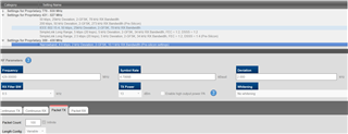
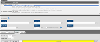
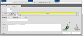
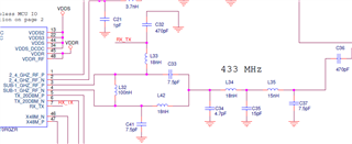
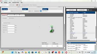
      (Matching circuit used in our design)

    We have modified "rfUARTBridge" SW as per our requirement. The setup used for validation is as mentioned below.

    PC <-> UART <-> RF board <-> Spectrum analyzer

    We are measuring the RF output in Spectrum analyzer by sending data through UART from the PC.

    Please let us know if any modification to be made in our config file or Circuit design to overcome the harmonics issue and accuracy of configured centre frequency

    Thanks

  • Please can you test using SmartRF Studio 7 (https://www.ti.com/tool/SMARTRFTM-STUDIO), and share the settings used? This helps isolate just the RF performance.

    Can you also measure one of the default PHYs to check if it is likely the PHY settings or the HW?

    To clarify the issue you are seeing, when you mention harmonics, it looks like you are actually talking about in-band spurs (rather than the harmonic power levels at 866 MHz, 1299 MHz, ect.) - is this correct?

    Regards,

    Zack

  • Hi Zack,

    We are able to run through SmartRF Studio and capture the Spectrum analyze charts for few default PHY configurations and our desired radio configuration as well. Please find the attachments below.

    Config 1:

    Spectrum Output:

    Config 2:

    Spectrum Output:

    Config 3: (Configuration that we would like to operate on)

    Spectrum Output:

    The spectrum shared yesterday was captured at antenna output and the configured bandwidth was 34.1MHz, but the spurs are outside the configured BW as well. We did not measure harmonics are distant frequency points.

    All the spectrum shared today are captured at the CC1311P3 output.

    Please check on our matching circuit shared yesterday and let us know if any tuning need to made to achieve better RF output at the antenna.

    Thanks!

  • Hi Zack,

    Please find the harmonics data captured at different frequency points attached here. Please let us know how we can reduce these harmonics at the RF output.

    Harmonics measured at RFIC output:

    Configuration in SmartRF studio:

    Please review this behavior and let us know the updates at the earliest.

    We appreciate your understanding on the urgency.

    Thanks!

  • Hi,

    This looks like you are using custom hardware - please can you confirm this?

    How did you determine the BOM values? For the 433 MHz band the recommended values (for 0201 components) are the following, from the LP-CC1352P7-4 reference design:


    L14 (in your design) is 7.5 nH - can you try changing it to 15 nH and share your results?

    Regards,

    Zack

  • Hi,

    Additionally, for your desired PHY settings you may need a wider RXBW setting to account for both the signal bandwidth (SBW) and the frequency error between the TX and RX devices (including crystal inaccuracies) - for guidance on how to check this and select a different RXBW setting if required, please refer to Section 4 of SWRA682 (Finding Settings for new PHYs for the CC13x0 and CC13x2 Family): https://www.ti.com/lit/swra682

    An App Note that explains selecting the required RXBW setting in another way is SWRA122 (CC11xx Sensitivity Versus Frequency Offset and Crystal Accuracy): https://www.ti.com/lit/swra122 - although it is written for the CC11xx devices, the underlying explanation is the same for the CC131x devices (so may help).

    It is likely that you will also need to adjust other PHY parameters as well, for which you can also refer to SWRA682.

    Regards,

    Zack

  • Hi,

    We have updated our HW based on the above input. Please find the measured harmonics attached herewith. We observed the harmonic level to be higher still. Please let us know on any additional improvements to be made to reduce the harmonics.

  • It looks like your fundamental is now ~17 dB higher compared to your previous measurements, suggesting the BOM improved the matching somewhat (from the information provided).

    You may have done this for the latest measurement, but to double-check:

    • Was this measurement performed by setting your device to transmit with an unmodulated (CW) carrier using SmartRF Studio, ideally using one of the default settings. If not, do you still observe these harmonic power levels if you perform that measurement?
    • The harmonics should not be that high if your measurements are correct - presumably you see roughly the same harmonic power levels if you transmit a CW signal at 433 MHz (as a sanity check)? The LP-CC1352P7-4 was extensively tested so we do not expect that performance.

    If the above issue persists, please submit your design for a HW review using:

    Sub-1 GHz Design Review Submission: https://www.ti.com/tool/SIMPLELINK-SUB1GHZ-DESIGN-REVIEWS

    That way we can take a closer look. 

    Regards,

    Zack

  • Hi,

    We have tested using LP-CC1311P3, we observed the below results.

    1. With modulated signal

    2. With unmodulated signal

    3. Configurations

    Please let us know if there can be difference in performance between LP-CC1311P3 and LP-CC1352P7-4 

  • Hi,

    The LP-CC1311P3 BOM is for 868/915 MHz operation; the performance at 433 MHz is not expected to work well with that design.

    The LP-CC1352P7-4 Sub-1 GHz BOM is designed for 433 MHz operation so should be used for 433 MHz testing.

    Regards,

    Zack