

Tool/software:
Background:
We initialized all GDOx outputs to High impedance (3-state) as specified by the Data sheet and operation is as expected. However, this product is a battery powered device and power consumption is extremely important when we went to produce a sample run an abnormality was noticed.
Issue:
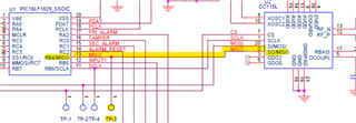
We noticed some current variance between boards and after some hardware debugging came across what appears to be SO/MISO acting as a floating pin when CS is not pulled low. The lab found a board that would draw ~47uA in its idle state but if they shorted GDO1 to ground the current would drop to 0.79uA.
Next Steps:
I haven't seen anywhere in the data sheet that suggests there should be a Pull-Up or Pull-Down on MISO. Is this standard procedure? Are we missing some other configuration step here? In the refrence design I don't see anything mentioned? What could be the cause of this?

