This thread has been locked.

If you have a related question, please click the "Ask a related question" button in the top right corner. The newly created question will be automatically linked to this question.

CC1101: Continous interrupt after power on

Part Number: CC1101


Tool/software:

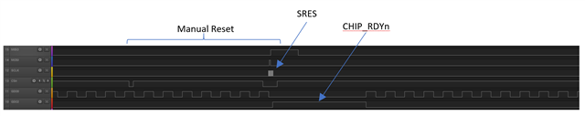
After the initial configuration of the CC1101 radio transceiver on the MCU side, an issue has been observed where the interrupt pin begins to generate interrupts at a very high frequency, approximately 135 kHz. This behavior occurs immediately following the CC1101 setup and seems to be triggered sporadically. The continuous stream of interrupts overwhelms the MCU's interrupt handling, effectively blocking the execution of other critical tasks. As a result, the system fails to feed the watchdog timer, leading to a forced MCU reset. However, the problem persists post-reset: upon reboot, the CC1101 continues to emit high-frequency interrupts, causing the board to enter a bootloop state. This renders the system non-functional until manual intervention or a hard reset of the CC1101 module is performed. This issue doesn't occur consistently, but it sometimes appears after power-up. What could be the root cause?

Here is the oscilloscope diagram of what is happening on this pin:

  • The CC1101 does not have any Interrupt pins.

    There are 3 GDO signals on the CC1101 that is configurable. If you read the datasheet, you will see that GDO0 is by default programmed to output CLK_XOSC/192 (26 MHz / 192 = 135 kHz).

    If you connect GDO0 to an input on your MCU, you should not enable interrupt on this input before you have programmed the CC1101 to output something useful for your application on that GDO pin.

    The data sheet lists all possible signals that can be output the the 3 GDO signals.

    BR

    Siri

  • I'm mean GDO2 pin of the CC1101

  • GDO2 is default programmed to be CHP_RDYn, and will not give out a 135 kHz clock unless you program it to do so (IOCFG2 = 0x3F) during what you refer to as the initial setup (you do not provide what register values you configure the device with).

    For all 3 GDO signal the same thing applies.

    If you have connected them to inputs on you MCU, you cannot enable any interrupts on these pins, before you have programmed the CC1101 to give out signals useful for your application at these pins.

    What signals do you want out on GDO0 and GDO2?

    Siri

  • This occurs before any register setup—simply configure the GPIOs on the MCU and power on the CC1101, and it begins automatically.

  • Have you made your own HW? If you have, have you made sure that the Power-On Reset Requirements are met?

    If not, you need to do a manual reset as describe in section 19.1.2 of the data sheet.

    Please perform a manual reset and provide plots of all SPI lines and GDO0 and GDO2 so that we can see what is going on.

    Below is a figure showing how it should look like.

    On my board I know that a Power-On Reset is perform so I already have the CLK_XOSC/192 out on GDO0 and CHIP_RDYn out on GDO2.

    After performing the manual reset as described in the data sheet, you will see that CHIP_RDYn is pulled high (chip is not ready during reset and the clock signal on GDO0 stops), and then when the chip becodes ready (CHIP_RDYn pulled low), the clock is started again.

    Please provide a similar plot from your test setup.

    Siri

  • So here is our schematic with CC1101:

    We will provide plot what's going on our hardware. 

  • also provide info regarding what reference design you have copied.

    Siri

  • Hi, we have followed the CC1101EM 868 – 915 MHz Reference Design (swrr045.zip)

    Here's the oscillogram after a manual power reset. Prescaled clock signals in antiphase immediately appear on GDO0 and GDO2 pins.

    Moreover, we are not able to reproduce the issue on startup with oscilloscope probes connected. We have tried probes with low parasitic capacitance e.g <3.8pF and this makes no difference. After disconnecting the probes the device is again more likely to fall into reboot loops caused by clock signal on GDO2 pins.

  • I do not understand your comment: “the device is again more likely to fall into reboot loops caused by clock signal on GDO2 pins”

    As I have said many times before, you need to disable interrupt on the Input pins on your MCU connected to GDO0 and GDO2.

    That way, it does not matter what is going on these pins, and they will not do anything with your application.

    If you look at the signals, they are not the same (out of phase with each other), so I do not think that this is signals coming from the CC1101 (if this was the CLK_XOSC/192

    Have you tested this on several devices?

    What happens after you program the IOCFG0 and IOCFG2 to something else? Does that change anything?

    You also should physically disconnect the GDO pins on the CC1101 from the MCU. What do you measure on these pins when they are not connected to anything?

    Siri

  • “the device is again more likely to fall into reboot loops caused by clock signal on GDO2 pins” - This issue arises because the interrupt on the MCU side for GDO2 is enabled before the CC1101 is initialized. As a result, the system can be blocked by a high-priority interrupt triggered by this pin, preventing proper configuration of the CC1101.

    As a workaround, we deferred enabling the GDO2 interrupt until after the CC1101 is initialized. This change resolved the issue. However, we are still investigating the root cause of the signal appearing on GDO2 immediately after power-on. This behavior is inconsistent—it does not occur every time, but when it does, it interferes with the system startup. In datasheet there is no information that on GDO2 we would expect also clock signal after power on. Is this behave properly?

  • It is not proper behavior to get anything other than CHIP_RDYn out on GDO2 after power on reset, so either the device is broken (ESD damage etc. ), or the signal is driven from the MCU.

    I did not get any answers to the rest of my questions.

    "

    Have you tested this on several devices?

    What happens after you program the IOCFG0 and IOCFG2 to something else? Does that change anything?

    You also should physically disconnect the GDO pins on the CC1101 from the MCU. What do you measure on these pins when they are not connected to anything?

    "

  • The signal for sure is not driven from MCU.
    1) Yes, we observed this on few devices.
    2) Yes, we can change this registers
    3) We didn't test that.