This thread has been locked.

If you have a related question, please click the "Ask a related question" button in the top right corner. The newly created question will be automatically linked to this question.

CC1101: WOR just using carrier

Part Number: CC1101
Other Parts Discussed in Thread: TEST2

Tool/software:

I have a system where we want to use a carrier sense WOR to wake up a system via GDO2

to save the limited battery power, the system itself is all asleep as best it can when it is not awake doing its job, which is very infrequent so the thing as a whole is essentially always asleep and we can get around 100uA system current at that point

I have managed to do a WOR configuration which will wake up using a packet broadcast from the remote end, but it had quite the stay on until packet received config so the power consumption is rubbish but I know it can work

I am now trying to do a WOR based on the carrier sense alone but with much longer timer values ie a 1Hz wake up where by I then put the remote end into a continuous tx mode to just blat RF into the environment for a couple of seconds such that the RSSI would then jump up and it would catch the power on 1 of the 1 second wakeup ticks. after that it can then go into a proper rx mode to do the real data exchange. there is no way to keep the 2 ends in time sync otherwise to try and lock the waking up window

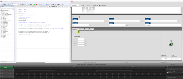
using a TI dev kit in continuous RX mode independently, i can see that my remote TX end is doing what it should as its RSSI is jumping up from the -110ish noise floor up to > -50dBm at least according to its chart

I have been through the GDO2, AGC and modem registers to try and get GDO2 to go active when i start the broadcast but seem at best to just end up with it bouncing on and off when the WOR timer period is happening

am I barking up the wrong tree here with this sort of approach ? or am i missing something obvious on what to present on GDO2 ( and the handling there of ) ?

// CC1101_Write (CC1101_IOCFG2, 0x24); // evt 0

// CC1101_Write (CC1101_IOCFG2, 0x25); // evt 1

// CC1101_Write (CC1101_IOCFG2, 0x14); // RSSI > threshold

// CC1101_Write (CC1101_IOCFG2, 0x07); // rx'd

CC1101_Write (CC1101_IOCFG2, 0x08); // Preamble Quality Reached.

CC1101_Write (CC1101_WORCTRL, 0x38 );

CC1101_Write (CC1101_PKTSTATUS, 6);

// CC1101_Write (CC1101_AGCCTRL2, 0x40); // MAGN = 24dB target

CC1101_Write (CC1101_AGCCTRL2, 0x43); // MAGN = 33dB target

CC1101_Write (CC1101_AGCCTRL1, 0x40); // carrier

CC1101_Write (CC1101_AGCCTRL1, 0x40 | 0x30 | 0x07 ); // carrier + 7

CC1101_Write (CC1101_MDMCFG2, 0x13); // GFSK 30/32 sync words

// CC1101_Write (CC1101_MDMCFG2, 0x14); // GFSK No preamble/sync, carrier-sense above threshold

// CC1101_Write (CC1101_MDMCFG2, 0x10); // no preamble

// CC1101_Write(CC1101_WOREVT1, 0x28 ); // should be 0.3 second with worctrl.event1=7

// CC1101_Write(CC1101_WOREVT0, 0xa0 );

CC1101_Write(CC1101_WOREVT1, 0x87 ); // should be 1 second with worctrl.event1=7

CC1101_Write(CC1101_WOREVT0, 0x76 );

CC1101_Write(CC1101_WORCTRL, 0x78);

CC1101_Write (CC1101_MCSM2, 0x0);

  • Hi,

    It is a national holiday so a (useful) response will be delayed until 2nd May.

    Regards,

    Zack

  • Not sure I fully understand what you are trying to implement here. The whole purpose of the WoR command is to check if there is something on the channel or not, and then stay in RX to receive a packet if there is.

    If you just want to figure out if there is a carrier or not on the air, you could use the WoR command to set up the proper wakeup interval for you application, and then you can output the CS signal on a pin. You can use this signal to wake up the MCU if there is a signal on the air, and then configure the device for normal RX.

    Siri

  • I want to be able to wake up a remote system but without the battery powered sensors waking up too often. the thought was to send a burst of carrier for 2 seconds or so with the WOR timer set at a second to minimise the current burden on the battery (the whole system very much is asleep for > 99% of the time ) and then the system would wake up, put the 1101 into RX mode and then the host will broadcast the message, knowing the remote end is awake and ready

    any attempt i make to try and use GDO2 to change based on RSSI simply leaves it just transitioning every time the event0 timeout kicks in / the thing wakes up and does its initial channel sensing, regardless of any RF energy on that channel

    I have been using the TI dev board in rx continuous mode as a "power meter" on the same channel so I know there is nothing about @-120dBm pretty much all the all the time bar some random occasional spikes from something else in the ether not of my control.

    i can move the event0 timer around up to its max value and the attached micro definitely wakes up from GDO 2 at this rate if I set the GDO2 config to 0x14 or 0x09 for instance ( and with the CCA to be RSSI based not constant )

    taking a different tack,

    using a 250ms event 0 wake up period isn't horrendous for the battery life and with GDO2 cfg set to 6, if i keep repeatedly sending messages at it from the host over a couple of seconds, the unit will generally wake up with a valid message - I don't care which message it caught, just that it got there

    however sometimes it must catch some sort of RF enough to switch the receiver on but does not toggle GDO2 or timeout as the current will jump up to around 15mA

    this is the init code

    CC1101_Write (CC1101_FIFOTHR, 0x47);

    CC1101_Write (CC1101_PKTCTRL0, 0x01);

    CC1101_Write (CC1101_FSCTRL1, 0x06);

    CC1101_Write (CC1101_FREQ2, 0x21);

    CC1101_Write (CC1101_FREQ1, 0x62);

    CC1101_Write (CC1101_FREQ0, 0x76);

    CC1101_Write (CC1101_MDMCFG4, 0xC8); // 10k data rate 100k rx filter bw

    CC1101_Write (CC1101_MDMCFG3, 0x93); // 10k data rate

    CC1101_Write (CC1101_MDMCFG2, 0x13); // gfsk | 30/32 sync word bits

    // CC1101_Write (CC1101_MDMCFG2, 0x14); // gfsk | no preamble/sync, carrier sense above

    CC1101_Write (CC1101_DEVIATN, 0x34);

    CC1101_Write (CC1101_FOCCFG, 0x16);

    CC1101_Write (CC1101_AGCCTRL2, 0x43);

    // CC1101_Write (CC1101_AGCCTRL2, 0xF3); // reduce the gains

    // CC1101_Write (CC1101_AGCCTRL1, 0x77); //

    CC1101_Write (CC1101_FSCAL3, 0xE9);

    CC1101_Write (CC1101_FSCAL2, 0x2A);

    CC1101_Write (CC1101_FSCAL1, 0x00);

    CC1101_Write (CC1101_FSCAL0, 0x1F);

    CC1101_Write (CC1101_TEST2, 0x81);

    CC1101_Write (CC1101_TEST1, 0x35);

    CC1101_Write (CC1101_TEST0, 0x09);

    // CC1101_Write (CC1101_WOREVT1, 0x06); // 45 msec

    // CC1101_Write (CC1101_WOREVT0, 0xC5);

    CC1101_Write (CC1101_WORCTRL, 0x38);

    // CC1101_Write (CC1101_WOREVT1, 0x0D); // 100 msec

    // CC1101_Write (CC1101_WOREVT0, 0xAC);

    CC1101_Write (CC1101_WOREVT1, 0x21); // 250 msec

    CC1101_Write (CC1101_WOREVT0, 0xFC);

    // CC1101_Write (CC1101_WOREVT1, 0x87); // should be 1 second with worctrl.event1=7

    // CC1101_Write (CC1101_WOREVT0, 0x76);

    // CC1101_Write (CC1101_WORCTRL, 0x78);

    CC1101_Write (CC1101_MCSM2, 0x1c); // gives 14msec rx timeout I think

    // CC1101_Write (CC1101_MCSM1, 0x10); // cca if rssi < threshold

    CC1101_Write (CC1101_MCSM0, 0x18);

    CC1101_Write (CC1101_IOCFG2, 0x06);

    // CC1101_Write (CC1101_IOCFG2, 0x07); // rx'd

    // CC1101_Write (CC1101_IOCFG2, 0x14); // RSSI > threshold

    // CC1101_Write (CC1101_IOCFG2, 0x09); // clear channel

    CC1101_Strobe (CC1101_SWORRST);

    CC1101_Strobe (CC1101_SWOR);

  • I did a test where I used the recommended settings from SmartRF Studio for the 2.4 kbps PHY, and then I enabled WoR with a 1 s wakeup interval, 12.5% duty cycle, and an CS threshold of -70 dBm (for test purposes)(see table 32 in the data sheee).

    Settings from Studio, and code is shown below:

    // Address Config = No address check 
    // Base Frequency = 867.999939 
    // CRC Autoflush = false 
    // CRC Enable = true 
    // Carrier Frequency = 867.999939 
    // Channel Number = 0 
    // Channel Spacing = 199.951172 
    // Data Format = Normal mode 
    // Data Rate = 2.39897 
    // Deviation = 5.157471 
    // Device Address = 0 
    // Manchester Enable = false 
    // Modulated = true 
    // Modulation Format = GFSK 
    // PA Ramping = false 
    // Packet Length = 255 
    // Packet Length Mode = Variable packet length mode. Packet length configured by the first byte after sync word 
    // Preamble Count = 4 
    // RX Filter BW = 58.035714 
    // Sync Word Qualifier Mode = 30/32 sync word bits detected 
    // TX Power = 0 
    // Whitening = false 
    // PA table 
    #define PA_TABLE {0x50,0x00,0x00,0x00,0x00,0x00,0x00,0x00}
    
    static const registerSetting_t preferredSettings[]= 
    {
      {CC1101_IOCFG0,      0x06},
      {CC1101_FIFOTHR,     0x47},
      {CC1101_PKTCTRL0,    0x05},
      {CC1101_FSCTRL1,     0x06},
      {CC1101_FREQ2,       0x21},
      {CC1101_FREQ1,       0x62},
      {CC1101_FREQ0,       0x76},
      {CC1101_MDMCFG4,     0xF6},
      {CC1101_MDMCFG3,     0x83},
      {CC1101_MDMCFG2,     0x13},
      {CC1101_DEVIATN,     0x15},
      {CC1101_MCSM0,       0x18},
      {CC1101_FOCCFG,      0x16},
      {CC1101_WORCTRL,     0xFB},
      {CC1101_FSCAL3,      0xE9},
      {CC1101_FSCAL2,      0x2A},
      {CC1101_FSCAL1,      0x00},
      {CC1101_FSCAL0,      0x1F},
      {CC1101_TEST2,       0x81},
      {CC1101_TEST1,       0x35},
      {CC1101_TEST0,       0x09},
    };
    
    void main(void)
    {
        // Initialize MCU and peripherals
        initMCU();
    
        // Write radio registers
        registerConfig();
        
        uint8 writeByte;
        
        // WoR settings for 1 s wakeup interval, 12.5% duty cycle
        writeByte = 0x18; cc1101SpiWriteReg(CC1101_MCSM0,   &writeByte, 1);
        writeByte = 0x38; cc1101SpiWriteReg(CC1101_WORCTRL, &writeByte, 1);
        writeByte = 0x00; cc1101SpiWriteReg(CC1101_MCSM2,   &writeByte, 1);
        
        writeByte = 0xB3; cc1101SpiWriteReg(CC1101_AGCCTRL2, &writeByte, 1); // CS threshold = -70dBm
        
        writeByte = 0x69; cc1101SpiWriteReg(CC1101_IOCFG0, &writeByte, 1); // Debug signal to show when device is awake
        writeByte = 14;   cc1101SpiWriteReg(CC1101_IOCFG2, &writeByte, 1); // CS  signal (RSSI > -70 dBm)
        
        trxSpiCmdStrobe(CC1101_SWOR);
        
        while(1);
    }

    For testing purposes, I had a transmitter that transmitted for around 2 s every time a button was pushed.

    As you can see prom the plots, the radio wakes up 125 ms every second. Every time a 2 s carrier is transmitted, the CS signal will be asserted.

    From your description, this is how I understand you want your system to work.

    Once you have gotten it to work with characterized settings and a strict CS threshold, you can start changing your settings and thresholds.

    In the data sheet we only have CS threshold settings for the 2.4 kbps and the 250 kbps PHYs, so if you use something other than that, you need to test different compinations of the  following parameters to find a suitable threshold for your application:

    AGCCTRL2.MAX_LNA_GAIN

    AGCCTRL2.MAX_DVGA_GAIN

    AGCCTRL2.MAGN_TARGE

    Siri

  • and this is purely based on the RSSI only? ie if I do not use a CC1101 but an RF generator at 868 and then turn that on CW to replicate your TX burst, it would do the same thing? I only as as MDMCFG2 still has the 30/32 preamble match enabled or is that ignored with something else in the config that I haven't spotted?  or is the point that by using mode 14 for the RSSI output on GDO 2, that would emulate your CS signal in the picture.

    is your transmission just the constant infinite packet length one? if so how does that work with pre-amble bits etc vs a non modulated RF carrier from a generator? 

  • The carrier sense signal (IOCFG2 = 14) does not care about what data is being transmitted. It only look at the signal strength, and asserts if the RSSI is above your programmed threshold.

    What  SYNC_MODE you use will not affect the CS signal.

    I tested the code with both sending packets with long preamble (2 s) and by sending unmodulated data for a given period of time.

  • ok I will try and test this tomorrow when I have access to the hardware again

    I did try essentially doing this already but I was getting transitions on GP2 when set to mode 14 every time it woke up regardless of what I did moving the thresholds around for MAGN_TARGET or the absolute / relative thresholds but it would certainly have been a different baud rate & bandwidth to your values.

    I only need to send << 1 FIFO worth of data for any broadcast so if it works reliably at 2.4k then it can stay at that

    the issue will be how much I can reduce the rx on time as ~15mA for 25% of the time is probably too high but as you say, I will prove it can work first and then "fiddle" to try and improve power consumption