This thread has been locked.

If you have a related question, please click the "Ask a related question" button in the top right corner. The newly created question will be automatically linked to this question.

CC1352R: Mikrocontroller stops working, oscillator without signal and debugging on running target not possible

Part Number: CC1352R


Tool/software:

Hello,

I received some of our devices using a CC1352R controller in an IOT application using BLE.

The devices stopped their advertising while power supply appears stable. Upon trying to connect to the mikrocontroller I always received the same error message, 

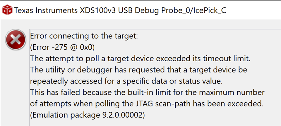
Debugging on a running target always worked in the past and when the device crushed for some reason it was at least stuck somewhere in the code.

I checked the signal from the external 48Mhz oscillator, there was nothing (0V). This explains the behaviour with the debugger, the controller seems dead.

However, when I power reset the device (forcefully unplugging the battery and connecting it again), the device starts working just fine.

Therefore I doubt that the oscillator itself might be broken.

After around 4 days it simply stops again. 

We use SimpleLink CC13x2 26x2 SDK v5.20.0.52 and cannot update to a newer one.

Could this problem be caused by a missbehaving step down converter leading to a brown out? Is there a way for the mikrocontroller to handle this issue?

  • Note that if RF is inactive, the 48 MHz xtal oscillator is turned off. The MCU is running on the internal RC oscillators in this case. 

    Do you have a watchdog in the system in case your code get stuck? 

  • Hello, thank you for the reply.

    Interesting about the oscillator depending on the RF activity.

    However, it should still be possible to debug on the running target no matter the clock source, right?

    We have a watchdog that checks responses from the two running tasks and resets the device in case one of them or both are stuck.

    In addition we have assertion handlers that trigger a clean reset of the device. 

  • Hi,

    Error 275 can be found at the Debugging JTAG page below:

    https://software-dl.ti.com/ccs/esd/documents/ccs_debugging_jtag_connectivity_issues.html

    I checked the signal from the external 48Mhz oscillator, there was nothing (0V). This explains the behaviour with the debugger, the controller seems dead.

    Your conclusion is correct; the absence of a clock will cause the CPU to be halted and inaccessible. However, does your system have an external oscillator fed into the device or is it a 48MHz crystal? If the latter, make sure you measure its activity with an oscilloscope using an active probe, since ordinary 10:1 oscilloscope probes load the crystal lines excessively and cause the oscillator to operate properly or stop. 

    After around 4 days it simply stops again.

    Regrettably, those issues that take very long time to manifest can be caused by a number of issues. These issues can range from very minimal memory leaks (rooted in SW) to externalities such as transients in power or clock lines, any high voltage discharges surrounding the product, especially affecting the RF path with its antenna and so on. 

    We have a watchdog that checks responses from the two running tasks and resets the device in case one of them or both are stuck.

    If the issue is very deterministic to 4 days of operation, my first natural suspicion falls in the SW. However, since you have a watchdog timer operating and tied to a couple of threads, I ask: are you using the internal or an external watchdog timer/supervisor IC? If using an external IC, what else is tied to it? I have seen external devices hold the main MCU hostage during an initialization stage where only a "physical" or external reset or even power up cleared all the devices and brought the system back to normal operation.

    I will try to think about additional scenarios and report back.

    Hope this helps,

    Rafael

  • Hello,

    thanks for your answer. 

    I did some experimenting and investigating the past few weeks.

    The device has a crystal and I can be sure that the oscilloscope can measure the clock correctly since I can clearly see the signal when I use a good working sample.

    Furthermore, I can now say that I have several devices and they all fail after different periods of time, some after 4 days, some after 3 weeks.

    The error pattern stays the same. The device simply stops working. 

    We measured the current and voltage but see no difference to a good working device. All test points and bus lines are inactive or inconspicuous, meaning there is no signal.

    The internal watchdog is used. I had a testing software to see if the watchdog is triggered and tries to reset or similar, but no. 

    I wonder if perhaps the chip has a memory defect somewhere.