This thread has been locked.

If you have a related question, please click the "Ask a related question" button in the top right corner. The newly created question will be automatically linked to this question.

CC1101: receiving Neptune R900 packets

Part Number: CC1101
Other Parts Discussed in Thread: TEST2

Tool/software:

Hi all! I have some conundrum with trying to receive my water meter packets using the chip.

This reference implementation for the protocol parser for RTL_433 seem to be dead easy to accomplish - https://github.com/NorthernMan54/rtl_433_ESP/blob/main/src/rtl_433/devices/neptune_r900.c

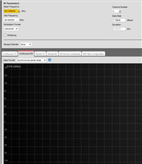
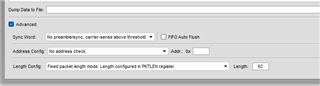
It is 912Mhz base freq, OOK modulation. The protocol itself is fixed-length ( 12 bytes ) packets

I got this register config via SmartRF

static const registerSetting_t preferredSettings[]= 
{
  {CC1101_IOCFG0,      0x06},
  {CC1101_FIFOTHR,     0x47},
  {CC1101_PKTLEN,      0x0C},
  {CC1101_PKTCTRL0,    0x04},
  {CC1101_FSCTRL1,     0x06},
  {CC1101_FREQ2,       0x23},
  {CC1101_FREQ1,       0x13},
  {CC1101_FREQ0,       0xB1},
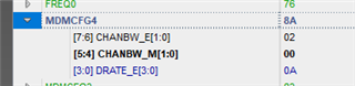
  {CC1101_MDMCFG4,     0xCA},
  {CC1101_MDMCFG3,     0x83},
  {CC1101_MDMCFG2,     0x37},
  {CC1101_MDMCFG1,     0x00},
  {CC1101_DEVIATN,     0x35},
  {CC1101_MCSM0,       0x18},
  {CC1101_FOCCFG,      0x16},
  {CC1101_AGCCTRL2,    0x43},
  {CC1101_WORCTRL,     0xFB},
  {CC1101_FREND0,      0x11},
  {CC1101_FSCAL3,      0xE9},
  {CC1101_FSCAL2,      0x2A},
  {CC1101_FSCAL1,      0x00},
  {CC1101_FSCAL0,      0x1F},
  {CC1101_TEST2,       0x81},
  {CC1101_TEST1,       0x35},
  {CC1101_TEST0,       0x09},
};

I can confirm that the chip stays in RX mode, and yet I'm not receiving any interrupt on GDO0.

So far I verified that:

- the R900 signals are coming through ( using RTL_SDR dongle and same antenna )

- the frequency and modulation that is detected in the packets matches my RF settings ( or should match ).

What else am I missing?

Thank you!

  • Hi Eugene, 

    I think that you are missing the sync word config: rtl_433_ESP/src/rtl_433/devices/neptune_r900.c at main · NorthernMan54/rtl_433_ESP · GitHub

    You can populate those values, or at least the first part of the syncword in that the SYNC1 and SYNC0 registers. 

    Regards,

    Arthur

  • Hi Arthur, thanks for the response. I did provide the sync word in the code itself, but for the sake of clarity I put everything into the config block. I can observe that the rtl-sdr dongle + rtl_433 gets the signals just fine while the chip doesn't seem to have anything. I verified the hardware and antenna.

    static const registerSetting_t preferredSettings[]=
    {
      {CC1101_IOCFG0,      0x06},
      {CC1101_FIFOTHR,     0x47},
      {CC1101_SYNC1,       0x66},
      {CC1101_SYNC0,       0xA9},
      {CC1101_PKTLEN,      0x0D},
      {CC1101_PKTCTRL0,    0x04},
      {CC1101_FSCTRL1,     0x08},
      {CC1101_FREQ2,       0x23},
      {CC1101_FREQ1,       0x13},
      {CC1101_FREQ0,       0xB0},
      {CC1101_MDMCFG4,     0xAA},
      {CC1101_MDMCFG3,     0x43},
      {CC1101_MDMCFG2,     0x33},
      {CC1101_MDMCFG1,     0x02},
      {CC1101_DEVIATN,     0x40},
      {CC1101_MCSM0,       0x18},
      {CC1101_FOCCFG,      0x16},
      {CC1101_AGCCTRL2,    0x43},
      {CC1101_WORCTRL,     0xFB},
      {CC1101_FREND0,      0x11},
      {CC1101_FSCAL3,      0xE9},
      {CC1101_FSCAL2,      0x2A},
      {CC1101_FSCAL1,      0x00},
      {CC1101_FSCAL0,      0x1F},
      {CC1101_TEST2,       0x81},
      {CC1101_TEST1,       0x35},
      {CC1101_TEST0,       0x09},
    };

  • Hi Eugene,

    Something I should I have asked before, are you able to receive the packets in SmartRF Studio 7?

    One interesting test would be to check if you can even detect the energy from the Neptune packet in Continous RX mode.

    Regards,

    Arthur

  • Arthur, hi!

    I think I solved the problem, at least I am getting some consistent 17 bytes packets. The issue was related to the preamble / sync word config, I had it as 11 ( match 30/32 bits ) but as Neptune transmits only 16 bits - that was doomed to fail. By changing the  MDMCFG2 to reflect that the preamble/sync shall match 15/16 bits - things started to happen!

    Thank you!

  • Hi! 

    I'm back with another challenge - I am able to receive something but apparently this something isn't what I'm looking for. My current register config is

        static const registerSetting_t preferredSettings[]= 
    {
      {CC1101_IOCFG0,      0x06},
      {CC1101_FIFOTHR,     0x47},
      {CC1101_SYNC1,       0xA9},
      {CC1101_SYNC0,       0x66},
      {CC1101_PKTLEN,      R900_PACKET_SIZE},
      {CC1101_PKTCTRL0,    0x04},
      {CC1101_FSCTRL1,     0x08},
      {CC1101_FREQ2,       0x23},
      {CC1101_FREQ1,       0x13},
      {CC1101_FREQ0,       0xB0},
      {CC1101_MDMCFG4,     0xAA},
      {CC1101_MDMCFG3,     0x43},
      {CC1101_MDMCFG2,     0x32},
      {CC1101_MDMCFG1,     0x12},
      {CC1101_DEVIATN,     0x40},
      {CC1101_MCSM0,       0x18},
      {CC1101_FOCCFG,      0x16},
      {CC1101_AGCCTRL2,    0x43},
      {CC1101_WORCTRL,     0xFB},
      {CC1101_FREND0,      0x11},
      {CC1101_FSCAL3,      0xE9},
      {CC1101_FSCAL2,      0x2A},
      {CC1101_FSCAL1,      0x00},
      {CC1101_FSCAL0,      0x1F},
      {CC1101_TEST2,       0x81},
      {CC1101_TEST1,       0x35},
      {CC1101_TEST0,       0x09},
    };


    So it seems to match part of the preamble 0xA9 0x66 and the received packet contains 0x69 0x65 as its first 2 bytes - that conforms to the preamble as defined in the R900 packet parser ( 0x55,0x55,0x55,0xA9,0x66,0x69,0x65 )

    But that is pretty much it - the rest of the data seem to be garbage, RSSI being reported as 0xDD after the packet is received.

    I have RTL_SDR compatible USB dongle that I run as 

    rtl_433 -vv -Y classic -f 912000000 -s 1m -R 228 -M level -M bits -M protocol -Y autolevel -F log -F json

    This is able to find certain R900 packets and parse them properly, but I can't match the raw data reported by rtl_433 tool to anything I find in the FIFO data buffer on CC1101.

    I wonder if there's a way to "debug" this issue somehow? I don't think that I can "peek" into a raw signal as received by the chip itself.

    Any help  / advice would be appreciated.

  • Hi Eugene,

    The issue here is that 0xA9 0x66 is a terrible sync word in itself (cf. (+) Mathematical method to calculate the best Sync word for CC1101 WOR as 0xD391 - /etc... RF (Read-Only) Forum - /etc... RF (Read-Only) - TI E2E support forums), so you may be getting lots of false positives.

    What you could do in order to avoid false positives is to set your CC1101 to receive fixed length packets (the 104 bits recommend in the github code).

    Regards,

    Arthur

  • Thank you, I understand that the sync word here isn't the best - but well, I have no options. I configured the CC1101 to have fixed packet length input. I opted out to have it 60 bytes to spot any "repeated" sequences so I can at least get some "stable" data packets that represent a valid R900 packet with just garbled encoding ( bit shifts etc ) - but I couldn't spot anything that is repeated.  At the same time my RTL dongle reliably receives the data packets from my water meter.

    What I wonder is - the R900 parser has the following statements:

    A transmission starts with a preamble of 0xAA,0xAA,0xAA,0xAB,0x52,0xCC,0xD2
    But, it is "zero" based, so if you insert a zero bit to the beginning of the bitstreamthe preamble is: - 0x55,0x55,0x55,0x55,0xA9,0x66,0x69,0x65

    So "in theory" I should be using 0xAB, 0x52 instead of 0xA9, 0x66 ? 

    Would that "leading zero bit" cause CC1101 to "shift" the rest of the bitstream as well?

  • Hi again, I did some further experiments - took two CC1101 chips from the same batch, connected them to the ESP32 boards, flashed the same firmware and started simultaneously ( tracing the ESP timestamps in the logs ).

    I would expect both boards to produce the same results, but in fact it doesn't hold:


    Board1: cc d2 cf e5 a4 d8 ce 55 c9 c9 e3 51 ae 6e 63 9c a3 33 a6 6c ad 55 54 3e

    Board2: cc d2 cb 65 a4 d8 ce 55 e9 c9 e3 51 ae 6c 63 9c a3 33 a6 7c ad 55 54 3e

    It almost looks like there's something slightly off with the baud rate and some bits are garbled.

    Do I need to fine-tune something in this case?

    My reg config, just in case:

    static const registerSetting_t preferredSettings[]= 
    {
      {CC1101_IOCFG0,      0x06},
      {CC1101_FIFOTHR,     0x47},
      {CC1101_SYNC1,       0xAB},
      {CC1101_SYNC0,       0x52},
      {CC1101_PKTLEN,      24},
      {CC1101_PKTCTRL0,    0x04},
      {CC1101_FSCTRL1,     0x08},
      {CC1101_FREQ2,       0x23},
      {CC1101_FREQ1,       0x13},
      {CC1101_FREQ0,       0xB0},
      {CC1101_MDMCFG4,     0xAA},
      {CC1101_MDMCFG3,     0x43},
      {CC1101_MDMCFG2,     0x32},
      {CC1101_MDMCFG1,     0x12},
      {CC1101_DEVIATN,     0x40},
      {CC1101_MCSM0,       0x18},
      {CC1101_FOCCFG,      0x16},
      {CC1101_AGCCTRL2,    0x43},
      {CC1101_WORCTRL,     0xFB},
      {CC1101_FREND0,      0x11},
      {CC1101_FSCAL3,      0xE9},
      {CC1101_FSCAL2,      0x2A},
      {CC1101_FSCAL1,      0x00},
      {CC1101_FSCAL0,      0x1F},
      {CC1101_TEST2,       0x81},
      {CC1101_TEST1,       0x35},
      {CC1101_TEST0,       0x09},
    };
  • Hi Eugene, 

    I would almost tend to think that this bit error may be caused by the bandwidth setting.

    What if you increase it to 200 KHz?

    Regards,

    Arthur

  • Hi, thanks for the hint! I tried that but basically got the same results, not much difference. The frustrating part is that I can't reproduce the signal myself so it offer me somewhat limited options for debugging as I literally have to wait for these data transfers to happen.

    What I did now - increased the size of packet to 60 bytes, just to observe whether there's some trailing data - and it seems that there's indeed something. For example, most of the packets have quite distinguishable gaps ( sequence of 00 00 00 ) that forms some pattern, which is consistent among the different boards:

    Board 1:

    cc d2 df 65 a4 d8 e4 de  31 c9 e3 53 4c 35 3c 6c
    aa 37 7c 72 a7 8b 92 3e  00 00 00 00 00 00 00 00
    cc 29 fb 3f 10 03 fb 3f  b2 dc 06 00 9c 34 40 3f
    00 00 00 00 30 5c fb 3f  00 00 00 00 00 00      

    Board 2:

    cc d2 dd e5 a4 d8 e5 4e  31 c9 e3 53 4e 3f 3c 6c
    aa 33 76 32 a7 8b 92 3e  00 00 00 00 00 00 00 00
    cc 29 fb 3f 10 03 fb 3f  a8 dc 06 00 9c 34 40 3f
    00 00 00 00 30 5c fb 3f  00 00 00 00 00 00      

    I'm not quite sure what to make of it, it doesn't look like noise or random signal, but why would 2 identical boards receive something that has almost 50% of overlap not only in data, but also in positions - I am really puzzled by this.

  • Hi,

    the signal myself

    Actually, that is something you could do. You could try transmitting a similar packet from the CC1101 (carefully, without antennas at a very low TX power), and compare the captured signal from your SDR using that software, for instance: 

    GitHub - jopohl/urh: Universal Radio Hacker: Investigate Wireless Protocols Like A Boss

    And see where it may differ.

    Regards,

    Arthur