This thread has been locked.

If you have a related question, please click the "Ask a related question" button in the top right corner. The newly created question will be automatically linked to this question.

CC1312PSIP: Migration project from CC1310 and CC1312R. RF problem.

Part Number: CC1312PSIP
Other Parts Discussed in Thread: CC1312R, CC1310, , SYSCONFIG,

Tool/software:

Hi,
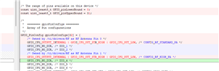
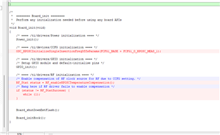
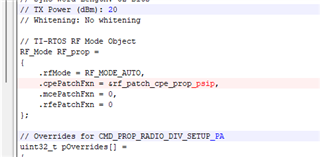
I am moving projects from CC1312R and CC1310 to CC1312PSIP. Most of it already working, except for radio communication. I don't know how to control DIO0 and DIO3 outputs.

Currently for CC1312 we are using SDK 4.10.0.78 and 3.40.0.02. For CC1310 4.10.1.01 and 3.20.0.23. The transition to newer SDK is very problematic for us.

Best regards,

  • Hi Jakub,

    As you maybe can see, the DIO0 and DIO3 pins are internally owned by the RF driver on the CC1312PSIP:

    Compared to the CC1312R project, there is also a special rfDriverCallbackAntennaSwitching callback:

    /*
     * ======== Antenna switching ========
     */
    /*
     * ======== rfDriverCallbackAntennaSwitching ========
     * Sets up the antenna switch according to the TX power table PA type.
     *
     * Truth table:
     *
     * Path       DIO0  DIO3 
     * ========== ===== ===== 
     * Off        0     0
     * STANDARD PA 1     0
     * HIGH PA    0     1
     */
    void __attribute__((weak)) rfDriverCallbackAntennaSwitching(RF_Handle client, RF_GlobalEvent events, void *arg)
    {
    
        if (events & RF_GlobalEventRadioSetup) {
            /* Switch off all paths. */
            GPIO_write(CONFIG_RF_STANDARD_PA, 0);
            GPIO_write(CONFIG_RF_HIGH_PA, 0);
    
            /* Decode the current PA configuration. */
            RF_TxPowerTable_PAType paType = (RF_TxPowerTable_PAType)RF_getTxPower(client).paType;
    
            if (paType == RF_TxPowerTable_HighPA) {
                /*
                * Mux GPIOs to RF Core signals:
                * - High PA    --> HIGH_PA
                * - LNA enable --> STANDARD_PA
                */
                GPIO_setConfigAndMux(CONFIG_RF_STANDARD_PA, GPIO_CFG_OUTPUT, IOC_PORT_RFC_GPO0);
                GPIO_setConfigAndMux(CONFIG_RF_HIGH_PA, GPIO_CFG_OUTPUT, IOC_PORT_RFC_GPO3);
            } else {
                /* RF Core active --> 5_DBM */
                GPIO_write(CONFIG_RF_STANDARD_PA, 1);
            }
        }
        else if (events & RF_GlobalEventRadioPowerDown) {
            /* Switch off all paths. */
            GPIO_write(CONFIG_RF_STANDARD_PA, 0);
            GPIO_write(CONFIG_RF_HIGH_PA, 0);
    
            /* Reset the IO multiplexer to GPIO functionality */
            GPIO_setConfigAndMux(CONFIG_RF_STANDARD_PA, GPIO_CFG_OUTPUT, IOC_PORT_GPIO);
            GPIO_setConfigAndMux(CONFIG_RF_HIGH_PA, GPIO_CFG_OUTPUT, IOC_PORT_GPIO);
        }
    }


    and additional temperature compensation settings:

    as well as dedicated CPE patch for the PSIP device + overrrides:

    My point being, I strongly recommend you to update to the latest SDK if possible.

    Regards,

    Arthur

  • Hi Arthur,

    Thank you for your answer.

    We took your advice and started migrating projects to the latest SDK. Unfortunately, new problems have appeared. The most serious one is that we use EasyLink, and the new SDKs do not support it. Is it possible to add EasyLink by copying directories from the old project, or in some other way?

  • Hi Marcin, 

    I must say that I have never tried porting Easylink to a newer SDK version. What we recommend is to use rflib directly, as it is more flexible.

    Are there any Easylink specific features that you are using?

    Regards,

    Arthur

  • Hi, Arthur

    I copied the EasyLink files from the old skd to the new one and got the project to a state where it compiles. I haven't tested if it works yet.

    We use 14 EasyLink functions in our projects:
    EasyLink_init()
    EasyLink_transmitAsync()
    EasyLink_transmitCcaAsync()
    EasyLink_receiveAsync()
    EasyLink_abort()
    EasyLink_enableRxAddrFilter()
    EasyLink_getIeeeAddr()
    EasyLink_setFrequency()
    EasyLink_getFrequency()
    EasyLink_setRfPower()
    EasyLink_getRssi()
    EasyLink_getAbsTime()
    EasyLink_setCtrl()
    EasyLink_Params_init()

    We don't use 4 functions:
    EasyLink_transmit()
    EasyLink_receive()
    EasyLink_getRfPower()
    EasyLink_getCtrl()

    Regards,

    Marcin.

  • Hi Marcin,

    I will try to summarize how you can replace the Easylink methods:

    • EasyLink_enableRxAddrFilter
      • This one can be setup by writing the RF_cmdPropRx addressX values and the pktConf.bCheckAddress bit 
    • EasyLink_receiveAsync
      • As it in done the the rfPacketRx example and EasyLink: rfPacketRx
      • You will get a callback with the packet content in the rx entry
    •  EasyLink_abort
    • EasyLink_setFrequency/getFrequency
      • Get/Set the contents of RF_cmdFs
    • EasyLink_setRfPower
    • EasyLink_getRssi
      • Either append the RSSI to the received packet with bAppendRssi in RF_cmdPropRx (preferred)
      • Use RF_getRssi
    • EasyLink_getAbsTime
    • For the CCA commands, use command chains as shown in rfListenBeforeTalk
      • In summary, use Carrier Sense to detect energy, then transmit if there is no energy.

    Let me know if that helps.

    Regards,

    Arthur

  • Hi, Arthur

    Currently I see that the above Easy Link issue is just the tip of the iceberg when migrating projects. The new SDK does not have
    #include <ti/drivers/PIN.h>
    The newer version has the following changes:
    #include <ti/drivers/UART.h>            ->#include <ti/drivers/UART2.h>
    #include <ti/display/DisplayUart.h>        ->#include <ti/display/DisplayUart2.h>
    #include <ti/drivers/spi/SPICC26XXDMA.h>    ->#include <ti/drivers/spi/SPICC26X2DMA.h>
    There are probably more similar changes that I haven't noticed yet, since I'm currently working on the easiest project to migrate.

    Regards,

    Marcin.

  • Yes, indeed, PIN has been replaced by GPIO (for the better, if you ask me). Here is the explaination: (+) LAUNCHXL-CC1310: GPIO v PIN driver? What are the differences? Which one is recommended? - Sub-1 GHz forum - Sub-1 GHz - TI E2E support forums . Same goes for UART2.

    Regards,

    Arthur

  • As you can see from the posts above, it takes a lot of work to get the software to compile after switching to the new SDK. Even more will be needed to run and test it. Meanwhile, when my superiors decided to use the CC1312PSIP, the information they had indicated that the migration from CC1312R to CC1312PSIP should be much easier than the migration from CC1310 to CC1312R. Compare topic e2e.ti.com/.../cc1312psip-migrating-from-cc1312r-to-cc1312psip

    In connection with the above, we return to the concept of staying with the old SDK, with which we currently have only two problems:
    - Shortly after transmission, we are unable to receive data correctly when the devices are further than 3cm apart
    - transmission takes place at a frequency 100KHz higher than the one set in the program.

  • HI Marcin,

    Again, I do not recommend you to go that way, we do not have support for the CC1312PSIP in that SDK version, as the device did not exist yet. You will spend more time trying to get the device to work on the older SDK than migrating.

    I am posting here our migration guides: Documentation Overview

    By the way, that 100 KHz deviation would indicate a wrong XOSC_CAPARRAY_DELTA configuration.

    Regards,

    Arthur

  • Hello Arthur,
    Jakub, when creating the topic, wrote that we are moving projects from CC1312R and CC1310 to CC1312PSIP.

    We are only moving some of the projects. At the moment, it is not possible to move all projects to CC1312PSIP, or even to the new SDK. The new SDK does not support CC1310. Since we use it in a 5x5mm housing (CC1310F128RHBR), there is also no way to replace it with CC1312R without modifying the hardware.

    In addition, all of our projects implemented on CC13* microcontrollers have most of the source files in common. The most extensive project on CC1310 currently has only 4KB of free FLash memory and Cache disabled, with --opt_level=2. Such a small amount of free memory already causes problems when debugging the software.
    In connection with the above, the following questions arise:
    - Is there a plan to introduce a pin-for-pin compatible replacement for the CC1310F128RHBR?
    - What effect will replacing PIN with GPIO have on memory usage and speed in projects working on the CC1310
    Regards,
    Marcin.

  • Hi Marcin ,

    I understand. In any way, you definitely have to keep using the CC13xx 4.20 SDK for the CC1310. The CC13xx (LOWPOWER-F1) one, are the CC13x2 SDK (LOWPOWER-F2) support different families.

    Are you using the CCS compiler for your CC1310 project?

    For your two questions:

  • Hi, Arthur

    I am using CCS 10.4.0.
    Ti v18.12.5.LTS or Ti v20.2.4.LTS compiler

    When working with the new SDK 8.3 I am using CCS 12.8.1, and TI CLang v3.2.2.LTS compiler

  • Hi Marcin,

    Now that you have the communication working with the CC1312PSIP working, thanks to the XOSC_CAPARRAY adjustement, let me know if we should keep this thread open.

    Regards,

    Arthur

  • Hi, Arthur

    I managed to establish communication, but only between the two projects. Work on the software is still ongoing, including tests, so far there has only been a symbolic amount. I am afraid that another problem may pop up in the coming weeks. If this actually happens and you close this topic, I will have to open a new topic.

    Furthermore, when time permits, I plan to describe here a bit of my experiences in this topic.

    Regards,
    Marcin.

  • Hi Marcin,

    I will leave that topic open then.

    Regards,

    Arthur

  • I'm sending changes to the project configuration that I made when converting the third project from CC1312R to CC1312PSIP. 
    I based it on the second project, where the transmission was already working and at SDK 4.10.0.78.

    3rd project - Properties: 

    • General/Products/Add/SysConfig 1.23.1
    • addition predefine Device_CC1312PSIP

    3rd project

    • adding a common file to the project containing, among others, the following functions:
          rfDriverCallback() which calls the function
          rfDriverCallbackAntennaSwitching() - RF switch support.

    Related to 3rd project Tirtos / Properties

    • General/Products -> change SDK at 4.10.00.78
          This change required the following changes to the sources:
          change ClockP_tickPeriod at Clock_tickPeriod
          change with UART2

    Sysconfig:

    • TI Drivers/Power/Enable Policy/ ON
    • TI Drivers/RF:
          RF.globalCallbackFunction = "rfDriverCallback";
          RF.globalEventMask        =
          ["RF_GlobalEventInit","RF_GlobalEventRadioPowerDown","RF_GlobalEventRadioSetup"];
    • TI Driver/Temperature -> ON
    • RF DEsign/Front-end for Sub-1 GHz == Internal Bias, Diferential RF
    • TI Drivers/Power - Restoring the default configuration
    • TI Devices/ Device Configuration:
          HF Clock Source -> change from External 48MHz TCXO at 48 MHz XOSC_HF
              I still do not understand why after the above change I still need to have TI DRIVERS/Power/
              Enable TCXO Function=Power_enableTCXO enabled.
              Without this the transmission does not work. The device probably hangs. So far I have not found the reason.
          Force VDDR - on
    • TI Drivers/RTOS -> Remove
    • RF Stack/EasyLink/Receive/Configure settings for receive operations - > Default
  • We do not use power above 14dB (25mW)
    Changes in files common to many projects:

    void Board_initHook()
    {
    ...
    #   ifdef Device_CC1312PSIP
        Board_init_rf_switch();
    #   endif  //#ifdef Device_CC1312PSIP
    ...
    }
    
    
    #ifdef Device_CC1312PSIP
    /*
     *  ======== PIN ========
     */
    /* RF Antenna Pin 0, (DIO0) Substitution, because there is no DIO0 for CC1312R, and in CC1312PSIP we have to use it */
    #define CONFIG_RF_STANDARD_PA    0x00000000
    /* RF Antenna Pin 1, (DIO3) */
    #define CONFIG_RF_HIGH_PA    0x00000003
    #endif //#ifdef Device_CC1312PSIP
    
    
    /*
     *  ====================== RF_switch ======================
     */
    
    #include <ti/drivers/rf/RF.h>
    #include <ti/drivers/PIN.h>
    #include <ti/drivers/pin/PINCC26XX.h>
    
    #ifdef Device_CC1312PSIP
    const PIN_Config antennaConfig[] =
    {
        /* RF Antenna Pin 0, (DIO1) */
        CONFIG_RF_STANDARD_PA | PIN_GPIO_OUTPUT_EN | PIN_GPIO_LOW | PIN_PUSHPULL | PIN_DRVSTR_MAX,
        /* RF Antenna Pin 1, (DIO3) */
        CONFIG_RF_HIGH_PA | PIN_GPIO_OUTPUT_EN | PIN_GPIO_LOW | PIN_PUSHPULL | PIN_DRVSTR_MAX,
        PIN_TERMINATE
    };
    static PIN_Handle antennaPins;
    static PIN_State antennaState;
    
    void Board_init_rf_switch(void)
    {
        if (PIN_init(antennaConfig) != PIN_SUCCESS) {
            /* Error with PIN_init */
            while (1);
        }
        antennaPins = PIN_open(&antennaState, antennaConfig);
    }
    
    
    /*
     * ======== rfDriverCallbackAntennaSwitching ========
     * Function to handle antenna switching.
     */
    void rfDriverCallbackAntennaSwitching(RF_Handle client, RF_GlobalEvent events, void *arg)
    {
        if(events & RF_GlobalEventInit) {
            // Perform action for this event
            //antennaPins = PIN_open(&antennaState, antennaConfig);
        }
        else if (events & RF_GlobalEventRadioSetup) {
            // > Set pin output value manually
            PINCC26XX_setOutputValue(CONFIG_RF_STANDARD_PA, 0); // Low
            PINCC26XX_setOutputValue(CONFIG_RF_HIGH_PA, 0); // Low
            PINCC26XX_setOutputValue(CONFIG_RF_STANDARD_PA, 1); // High
        }
        else if (events & RF_GlobalEventRadioPowerDown) {
            PINCC26XX_setOutputValue(CONFIG_RF_STANDARD_PA, 0); // Low
            PINCC26XX_setOutputValue(CONFIG_RF_HIGH_PA, 0); // Low
    
            // > Mux pin to be driven/controlled by the RF Core
            // > (RFC GPIO0 is here only used as an example)
            //PINCC26XX_setMux(antennaPins, CONFIG_RF_STANDARD_PA, PINCC26XX_MUX_RFC_GPO0);
    
            // > Mux pin to be controlled manually (i.e. release RF Core control)
            PINCC26XX_setMux(antennaPins, CONFIG_RF_STANDARD_PA, PINCC26XX_MUX_GPIO);
            PINCC26XX_setMux(antennaPins, CONFIG_RF_HIGH_PA, PINCC26XX_MUX_GPIO);
        }
    
    /*
     *  ======== rfDriverCallback ========
     *  Handle events triggered by the RF driver for custom / application specific behavior.
     */
    void rfDriverCallback(RF_Handle client, RF_GlobalEvent events, void *arg)
    {
        if(events & RF_GlobalEventInit) {
            // Perform action for this event
        }
        else if (events & RF_GlobalEventRadioPowerDown) {
            // Perform action for this event
        }
        else if (events & RF_GlobalEventRadioSetup) {
            // Perform action for this event
        }
    
        rfDriverCallbackAntennaSwitching(client, events, arg);
    
    }

    Changes specific to the third project

    • Removing one of the PIN_open() function calls. The change was necessary after switching to a SysConfig configuration in the project. When it was called, the microcontroller hung up because the pins it used had already been opened in a file generated by SysConfig, namely ti_drivers_config.c
    • /*
       *  ======== Power_enableTCXO ========
       *
       * This is a dummy plug added to avoid having to create a new tirtos project. 
       * This way there is one common tirtos for many projects.
       */
      void Power_enableTCXO(bool turnOn)
      {
          ;
      }
  • The third project brought back a problem I was familiar with, which had already been solved with the second project. When the device transmits and then receives, it has a very small range - about a meter. The RSSI in the device it communicates with is at a very good level, and on the LAUCPAD LP-EM-CC1312PSIP no better than -90dB. It is true that temperature compensation has not yet been implemented, but I do not think it matters, because the difference in the operating frequency of the devices is only 6KHz.


    Is it possible that this problem is related to the different time interval between transmitting and receiving?
    I have compared both projects carefully and no other idea comes to my mind at the moment.