This thread has been locked.

If you have a related question, please click the "Ask a related question" button in the top right corner. The newly created question will be automatically linked to this question.

CC2674R10: Standby mode and energytrace++

Part Number: CC2674R10
Other Parts Discussed in Thread: CC3351, SYSCONFIG, ENERGYTRACE

Tool/software:

Hello TI Community,

I'm developing a low-power application on the CC3351 that requires the device to spend most of its time in standby mode. The system includes:

  • Sensor Controller with ADC and capacitive touch tasks
  • CC3351 configured as an MQTT client
  • FreeRTOS-based application

Issue Description: Currently, I'm attempting to verify standby mode operation with a simplified test case (sensor controller and MQTT functionality disabled). However, the device appears to remain in active mode despite implementing the following main loop:

while (1) {
    vTaskDelay(pdMS_TO_TICKS(500));
    
    switch(state) {
        case STATE_INIT:
            state = STATE_SLEEPING_WITH_TOUCH;
            break;
            
        case STATE_SLEEPING_WITH_TOUCH:
            if (++debugCounter >= 20) {
                debugCounter = 0;
                // Additional debug code here
            }
            break;
    }
}

Debugging Steps Taken:

  1. Power Constraints Verification:
void debug_constraints() {
    uint_fast32_t constraints = Power_getConstraintMask();
    LOG_INFO("Current constraints: 0x%08X", constraints);
    
    if (constraints & (1 << PowerCC26XX_DISALLOW_STANDBY)) {
        LOG_INFO("STANDBY is BLOCKED");
    }
}

Output: [14:28:06.458] [MAIN::INFO] Current constraints: 0x00000000

  1. Standby Latency Check:
uint32_t standbyLatency = Power_getTransitionLatency(PowerCC26XX_STANDBY, Power_TOTAL);
LOG_INFO("Standby latency: %d us", standbyLatency);

Output: [14:30:08.027] [MAIN::INFO] Standby latency: 1000 us

  1. Clock Source Verification:
LOG_INFO("---------------------------Testing LF and HF quartz-----------------------------------");
OSCHF_TurnOnXosc(); 

// Ensure switch to XOSC
while (!OSCHF_AttemptToSwitchToXosc()) {
    vTaskDelay(pdMS_TO_TICKS(10));
}

LOG_INFO("HF crystal real amplitude : %d mv", OSCHF_DebugGetCrystalAmplitude());
LOG_INFO("HF crystal expected amplitude : %d mv", OSCHF_DebugGetExpectedAverageCrystalAmplitude());

uint32_t hf_source = OSCClockSourceGet(OSC_SRC_CLK_HF);
if (hf_source == OSC_XOSC_HF) {
    LOG_INFO("HF crystal source: XOSC");
} else if (hf_source == OSC_RCOSC_HF) {
    LOG_INFO("HF crystal source: RC clock");
} else {
    LOG_ERROR("HF crystal source: Invalid configuration (value: %d)", hf_source);
}

uint32_t lf_source = OSCClockSourceGet(OSC_SRC_CLK_LF);
if (lf_source == OSC_XOSC_LF) {
    LOG_INFO("LF crystal source: XOSC");
} else if (lf_source == OSC_RCOSC_LF) {
    LOG_INFO("LF crystal source: RC clock");
} else {
    LOG_ERROR("LF crystal source: Invalid configuration (value: %d)", lf_source);
}
LOG_INFO("----------------------------------------------------------------------------------------");

Clock Verification Output:

[14:37:04.538] [MAIN::INFO] ---------------------------Testing LF and HF quartz-----------------------------------
[14:37:04.618] [MAIN::INFO] HF crystal real amplitude : 495 mv
[14:37:04.618] [MAIN::INFO] HF crystal expected amplitude : 465 mv
[14:37:04.618] [MAIN::INFO] HF crystal source: XOSC
[14:37:04.618] [MAIN::INFO] LF crystal source: XOSC
[14:37:04.618] [MAIN::INFO] ----------------------------------------------------------------------------------------

Observations:

  • No power constraints are active (0x00000000)
  • Both HF and LF clocks are successfully running on XOSC
  • Crystal amplitude is within expected range
  • Power policy is configured in SysConfig with appropriate settings
  • Unfortunately, EnergyTrace++ is not functional in the current CCS version, preventing direct power mode verification

Questions:

  1. Are there additional requirements beyond constraint clearing and clock configuration to enable automatic standby transitions?
  2. Could FreeRTOS task scheduling be preventing standby entry despite the 500ms delay?
  3. Is there a recommended method to verify standby mode entry without EnergyTrace++?

Any insights would be greatly appreciated. Thank you!

  • Hi,

    As a first step, in your main loop, instead of "vTaskDelay(pdMS_TO_TICKS(500));", can you try "usleep(500000);"?

    Thanks,
    Toby

  • Thank you for the quick response, I've already tried different sleep like osi_Usleep(), sleep(), usleep() method but this doesn’t change anything unfortunately.

  • Thanks for confirming.

    Is this custom hardware? 

  • Yes, it's custom hardware. I've already managed to get the system into standby mode with just a test using TI-RTOS, but I can't replicate the same behavior with FreeRTOS. The project also includes other components like the CC33xx, etc. I've identified that the main chip is consuming most of the power - when I hold it in reset I get around 20µA consumption, but 5mA when it's running.


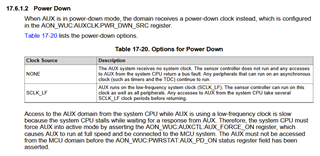
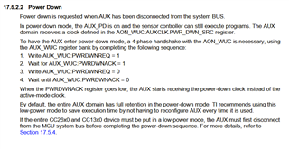
    I've seen in the documentation that we may need to disconnect the MCU BUS :

    And change the Power Down clock and some AUX :


    The documentation says to only use the TI provided API, but I don't know where I can find the documentation for the API for the AON / AUX and MCU bus.

    Thanks for helping

  • Regarding "TI provided API", the TI Drivers (including Power) are located here: C:\ti\simplelink_cc13xx_cc26xx_sdk_8_30_01_01\source\ti\drivers

    Typically the user application only needs to call Power_* functions declared in ti/drivers/Power.h, and then these will be translated to the device-specific function (in ti/drivers/power).

    Also, the Power driver itself is initialized by the default startup code.

  • okay that's why I was thinking, so you only need to call the command on the driver libs from TI, and do not required to change register directly ?

  • Yes, that is correct!

    While register read/write is possible to reach the same functionality, we try to reduce the complexity on code development by providing the TI Drivers.

  • Nice ! did you have some idea to debug the fact that I do no enter standby mode ? I've now make a small test program in my main: 

    int_fast16_t enterStandbyMode(uint32_t wakeupTimeMs, bool retainCache)
    {
        int_fast16_t status;
        uint32_t constraints;
       
        LOG_INFO("Preparing to enter standby mode...");
       
        // Check if standby is allowed
        constraints = Power_getConstraintMask();
        if (constraints & (1 << PowerCC26XX_DISALLOW_STANDBY)) {
            LOG_ERROR("Standby is blocked by constraint");
            return Power_ECHANGE_NOT_ALLOWED;
        }
       
        // Check if system is already transitioning
        if (Power_getTransitionState() != Power_ACTIVE) {
            LOG_ERROR("Power transition already in progress");
            return Power_EBUSY;
        }
       

        LOG_INFO("RTC start configure...");
        // Configure RTC wakeup if requested
        if (wakeupTimeMs > 0) {
            // Convert milliseconds to RTC ticks (32768 Hz)
            uint32_t rtcTicks = (wakeupTimeMs *2 * 32768) / 1000;
            uint32_t currentVal = AONRTCCurrentCompareValueGet();
           
            // Set channel 0 compare value
            AONRTCCompareValueSet(AON_RTC_CH0, currentVal + rtcTicks);
            AONRTCChannelEnable(AON_RTC_CH0);
           
            // Configure the RTC event to wake MCU
            AONEventMcuWakeUpSet(AON_EVENT_MCU_WU0, AON_EVENT_RTC_CH0);
        }
        LOG_INFO("RTC start configured OK");

       
        // Set cache retention constraint if needed
        if (retainCache) {
            Power_setConstraint(PowerCC26XX_RETAIN_VIMS_CACHE_IN_STANDBY);
        } else {
            Power_releaseConstraint(PowerCC26XX_RETAIN_VIMS_CACHE_IN_STANDBY);
        }
       
        // Use the Power driver to enter standby
        // The Power driver will handle all the low-level details
        status = Power_sleep(PowerCC26XX_STANDBY);
       
        if (status == Power_SOK) {
            LOG_INFO("Successfully woke from standby");
        } else {
            LOG_ERROR("Failed to enter standby: %d", status);
        }
       
        return status;
    }

    15:20:23.893] [MAIN::INFO] === Power Status ===
    [15:20:23.893] [MAIN::INFO] Constraints: 0x00000000
    [15:20:23.893] [MAIN::INFO] Transition state: ACTIVE
    [15:20:23.893] [MAIN::INFO] Active peripherals:
    [15:20:23.893] [MAIN::INFO] - GPIO: 1 dependencies
    [15:20:23.893] [MAIN::INFO] - UART0: 1 dependencies
    [15:20:23.893] [MAIN::INFO] ===================
    [15:20:23.893] [MAIN::INFO] Entering standby mode...
    [15:20:23.893] [MAIN::INFO] Preparing to enter standby mode...
    [15:20:23.893] [MAIN::INFO] RTC start configure...
    [15:20:23.893] [MAIN::INFO] RTC start configured OK
    [15:20:53.891] [MAIN::INFO] Successfully woke from standby
    [15:20:54.403] [MAIN::INFO] Entering standby mode...
    [15:20:54.403] [MAIN::INFO] Preparing to enter standby mode...
    [15:20:54.403] [MAIN::INFO] RTC start configure...
    [15:20:54.403] [MAIN::INFO] RTC start configured OK
    [15:21:24.403] [MAIN::INFO] Successfully woke from standby


    It's seem to enter the standby correctly but the consumption are still too high, I've also tried to close the UART but I still have a lot of power consumption, the GPIO dependency maybe prevent standby ? is there a way to find which GPIO is active ?

  • Is the RTOS started at this point?

    Taking a step back, I'd recommend starting with a simpler example to see how it enters standby. Such as an empty example (but remove the GPIO function calls in mainThread): https://dev.ti.com/tirex/explore/node?node=A__AHhWibQBN9XX39FT3iQlgw__com.ti.SIMPLELINK_LOWPOWER_F3_SDK__58mgN04__LATEST

  • Actually I've tried a very simple project with a while 1 with a sleep in my main-thread started by the main of the FREERTOS. But I still have way to much consumption (around 700uA, and I don't know if it really enter standby mode) also I don't how to make the energy trace ++ to work since I launch it and nothing show on the graph, this tools may be useful to know in which states the device is, the old energy trace can't do that.


    What is the actual difference between an empty project and my project with just a while loop with a delay on the main task ? 


  • EDIT : Actually it worked after a reset in the empty project where I get 19uA around of consumption, but in my main project I can reset cause it keep reseting at startup with a system reset reason. 

  • Hi Valentin,

    What is the actual difference between an empty project and my project with just a while loop with a delay on the main task ? 

    The difference is that empty doesn't directly call functions to enter standby; it calls sleep, then the RTOS will put the device in the lowest power state.

    Earlier I mentioned just calling the Power_* functions... I might stand corrected, in the case you are using an RTOS -- the RTOS will manage the power state of the device.

    Actually it worked after a reset in the empty project

    Glad to hear you got EnergyTrace working! In the past, I've found that the reset on the device is sometimes required after starting EnergyTrace but before starting the EnegyTrace measurement.

    in my main project I can reset cause it keep reseting at startup with a system reset reason

    What is the reset reason you see?

    Thanks,
    Toby

  • Thank you for the response, the Enegerytrace does not work but the device goes into standby in the empty project, I've tried to use my actual project and only make a while and sleep in the main thread, but I still have a lot of consumption so it may be an issue with the Free RTOS configuration I think.

    The reset reason is : PowerCC26X2_RESET_SYSTEM

  • I've tried to use my actual project and only make a while and sleep in the main thread, but I still have a lot of consumption

    Is this new consumption higher or lower than before?

    I believe that reset reason is typical if you do a hard reset (press reset button) -- so no concerns there.

  • Same as before, I have an other reset reason for button reset, the system reset is a reset in the chip I think since I do not see anything on my reset pin when it reset itself, I use this function to show the reset reason.

    void handleResetReason(PowerCC26X2_ResetReason resetReason)
    {
        // First print detailed info about the reset reason
        switch(resetReason)
        {
            case PowerCC26X2_RESET_SHUTDOWN_IO:
                LOG_INFO("Reset reason: WAKEUP FROM SHUTDOWN (IO event) [%d]", resetReason);
               
                // Special handling for wakeup from shutdown
                LOG_INFO("Releasing IO latches after shutdown wakeup");
                //PowerCC26X2_releaseLatches();
                break;
               
            case PowerCC26X2_RESET_SYSTEM:
                LOG_INFO("Reset reason: SYSTEM RESET (Software/Watchdog) [%d]", resetReason);
                break;
               
            case PowerCC26X2_RESET_TCK_NOISE:
                LOG_INFO("Reset reason: WAKEUP FROM TCK NOISE (JTAG interference) [%d]", resetReason);
                break;
               
            case PowerCC26X2_RESET_WARM_RESET:
                LOG_INFO("Reset reason: WARM RESET (Debugger) [%d]", resetReason);
                break;
               
            case PowerCC26X2_RESET_CLK:
                LOG_INFO("Reset reason: CLOCK LOSS [%d]", resetReason);
                break;
               
            case PowerCC26X2_RESET_VDDR:
                LOG_INFO("Reset reason: VDDR BROWNOUT [%d]", resetReason);
                break;
               
            case PowerCC26X2_RESET_VDDS:
                LOG_INFO("Reset reason: VDDS BROWNOUT [%d]", resetReason);
                break;
               
            case PowerCC26X2_RESET_PIN:
                LOG_INFO("Reset reason: PIN RESET [%d]", resetReason);
                break;
               
            case PowerCC26X2_RESET_POR:
                LOG_INFO("Reset reason: POWER ON RESET [%d]", resetReason);
                break;
               
            default:
                LOG_INFO("Reset reason: UNKNOWN [%d]", resetReason);
                break;
        }
    }
  • it may be an issue with the Free RTOS configuration

    What differences do you see in your FreeRTOS configuration vs the SDK empty example (where you saw low current consumption I presume)?

    The files to look into (after the project is built):

    1. <project>/Debug/syscfg/FreeRTOSConfig.h
    2. <project>/Debug/syscfg/ti_freertos_config.c
    Actually it worked after a reset in the empty project where I get 19uA around of consumption, but in my main project I can reset cause it keep reseting at startup with a system reset reason

    Can you describe further what you mean by the "reset" here?

    1. "...it worked after a reset in the empty project..."
    2. "...in my main project I can reset cause it keep reseting at startup..."

    From my understanding, 1) is talking about the empty project and the reset means you physically reset the device by pressing the pin and you see reset reason "an other reset reason for button reset", and 2) is your main project, and you keep seeing the device reset even though you don't intentionally press reset button with reset reason "PowerCC26X2_RESET_SYSTEM".

    Is this correct?

  • Hi thanks for the help and your time , the error was with some GPIO that was making the consumption very high ! Now I can achieve a 19uA consumption !