This thread has been locked.

If you have a related question, please click the "Ask a related question" button in the top right corner. The newly created question will be automatically linked to this question.

CC1312R: Oscillator stabilization time

Part Number: CC1312R
Other Parts Discussed in Thread: SYSBIOS
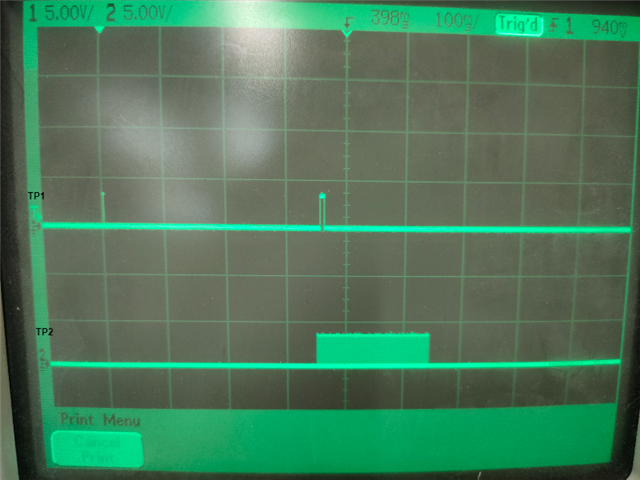
Tool/software:

After returning from standby mode, the RF, timer, UART, etc. are initialized and packets are sent. After the initialization, it takes about 30 ms for the timer interrupt to occur. Is this due to the oscillator stabilization time? Also, is there a way to shorten this time?
  • Hi Shingo,

    What timer interrupt are you talking about in your message?

    Regards,

    Arthur

  • Hi,

    Oscillator/XTAL bringup should be handled at device startup, and from what I've observed takes negligible time (probably < 30msec).

    Is your issue happening after the device has already started and some time has passed? E.g.

    1. Power on
    2. time passes > 30msec
    3. Timer interrupt observation

    Can you provide further info so we can better support you:

    1. SDK version
    2. SDK example which your project is based
    3. Sequence of steps to observe this behavior (ideally on a TI hardware, such as Launchpad)

    Thanks,
    Toby

  • This is the callback. The specific implementation is as follows:

    void timerCallback(Timer_Handle myHandle, int_fast16_t status)
    {
    TP2_HI;
        tick_1msec_counter++;
    TP2_LO;
        
    }

    void TIMER_Initialize( void )
    {
    /*
    * Setting up the timer in continuous callback mode that calls the callback
    * function every 1,000,000 microseconds, or 1 second.
    */
    Timer_Params_init(&timerParams);
    timerParams.period = 1000;
    timerParams.periodUnits = Timer_PERIOD_US;
    timerParams.timerMode = Timer_CONTINUOUS_CALLBACK;
    timerParams.timerCallback = timerCallback;

    timer0 = Timer_open(CONFIG_TIMER_0, &timerParams);

    if (timer0 == NULL)
    {
    /* Failed to initialized timer */
    while (1) {}
    }

    if (Timer_start(timer0) == Timer_STATUS_ERROR)
    {
    /* Failed to start timer */
    while (1) {}
    }

    }

  • 1.SDK simplelink_cc13xx_cc26xx_sdk_8_30_01_01

    2.base simplelink_cc13xx_cc26xx_sdk_8_30_01_01\examples\nortos\CC1312R1_LAUNCHXL\prop_rf\rfPacketRx

    3.Although this is a custom board, the RF section is the same as LAUNCHXL-CC1312R1.

    ccs ver  Version: 10.4.0.00006 

    The initial 30ms was a mistake; the time thought to be the oscillation stabilization time was 340ms.
    I will send the actual code and an image of the state on an oscilloscope.


    // Standby Entry

        g_eventFlag = 0;
        g_aonRtcEventFlag = 0;
        while( g_eventFlag == 0 && g_aonRtcEventFlag == 0 ){
            Power_idleFunc();
        }
    // Exit
    TP1_HI;
        g_eventFlag = 0;
        g_aonRtcEventFlag = 0;


        UART1_Initialize( BPS115200, STOP_1BIT, PARITY_EVEN, DATA_8BIT );
        TIMER_Initialize();
        PWM_Initialize();
        SPI1_init();
    TP1_LO;


    void timerCallback(Timer_Handle myHandle, int_fast16_t status)
    {
    TP2_HI;
        tick_1msec_counter++;
    TP2_LO;
        
    }

    void TIMER_Initialize( void )
    {
        /*
         * Setting up the timer in continuous callback mode that calls the callback
         * function every 1,000,000 microseconds, or 1 second.
         */
        Timer_Params_init(&timerParams);
        timerParams.period        = 1000;
        timerParams.periodUnits   = Timer_PERIOD_US;
        timerParams.timerMode     = Timer_CONTINUOUS_CALLBACK;
        timerParams.timerCallback = timerCallback;

        timer0 = Timer_open(CONFIG_TIMER_0, &timerParams);

        if (timer0 == NULL)
        {
            /* Failed to initialized timer */
            while (1) {}
        }

        if (Timer_start(timer0) == Timer_STATUS_ERROR)
        {
            /* Failed to start timer */
            while (1) {}
        }
        
    }


  • Hi Shingo,

    looking at your code I notice that your calling actively the power idle function. 

    while( g_eventFlag == 0 && g_aonRtcEventFlag == 0 ){
            Power_idleFunc();
        }

    Instead you should let the power driver transition the device to sleep by pending on a semaphore or by letting the MCU being idle differently.

    Kind regards,
    Theo

  • Can you provide the exact code for this answer?

    Instead you should let the power driver transition the device to sleep by pending on a semaphore or by letting the MCU being idle differently.

    This is implemented as a process to reduce current consumption in standby mode. The input signal interrupt and aonRTC interrupt are used to return from standby mode. The problem is, when the timer is initialized upon return, why is the timing of the timer callback delayed? Does anyone know if this is due to the XOSC stabilization wait time?
    
    
  • Hi Shingo,

    you can just pend on an empty while loop and the power driver should detect that the MCU is idle and transition to sleep.

    Please explain which delay you mean. In the shared oscilloscope plot I see two toggles for TP1 and after the second I see the activity on TP2.

    Kind regards,
    Theo

  • The oscilloscope waveform was taken after exiting standby.

    The first TP1 ON is the following part in the code.
     
    TP1_HI;
        g_eventFlag = 0;
        g_aonRtcEventFlag = 0;


        UART1_Initialize( BPS115200, STOP_1BIT, PARITY_EVEN, DATA_8BIT );
        TIMER_Initialize();
        PWM_Initialize();
        SPI1_init();
    TP1_LO;
     
    Within it, we execute 
    TIMER_Initialize();
    and register the Timer callback there.
    TP2 is output within the callback.
    void timerCallback(Timer_Handle myHandle, int_fast16_t status)
    {
    TP2_HI;
        tick_1msec_counter++;
    TP2_LO;
        
    }
    I don't understand why it takes 340 ms from TIMER_Initialize() until TP2 occurs.
  • Hi Shingo,

    what is the second TP1 pulse in your capture (the one right before TP2 activity)?

    To understand better what is going on you could connect TI Logger and enable the power driver debug statements. 

    This would help us to understand if the transitions are trigger as you expect.

    https://dev.ti.com/tirex/explore/node?node=A__AUtBCHw9KYI99xItuPjn4w__com.ti.SIMPLELINK_ACADEMY_CC13XX_CC26XX_SDK__AfkT0vQ__LATEST 

    Did you try to run it with an empty while loop instead of calling  Power_idleFunc();? does the device is set to sleep by the power driver?


    Kind regards,
    Theo

  • The second TP1 is the timing when the packet is actually transmitted over RF.

    In the transmission function, RF_runCmd is used, and it has been confirmed that packets are sent.

    I determined that the power driver had set the device into standby mode by inserting an ammeter into the power line and measuring the current, which dropped to 8μA, so I concluded that the device was in standby mode.
    To get to this point, I used Power_getDependencyCount to find out which modules were preventing standby.

    In reality, after stopping and closing each module, I loop Power_idleFunc();.
    
    Is there any problem with transitioning to standby mode with Power_idleFunc();?

    Actual implementation function
     ↓
    void SleepSystem(){

        SPI1_close();
        TIMER_Close();
        PWM_Close();
        LED_ALL_OFF;
        UART1_Close();
    // Standby Entry
        g_eventFlag = 0;
        g_aonRtcEventFlag = 0;
        while( g_eventFlag == 0 && g_aonRtcEventFlag == 0 ){
            Power_idleFunc();
    
    
        }
    // Exit
    TP1_HI;
        g_eventFlag = 0;
        g_aonRtcEventFlag = 0;


        UART1_Initialize( BPS115200, STOP_1BIT, PARITY_EVEN, DATA_8BIT );
        TIMER_Initialize();
        PWM_Initialize();
        SPI1_init();
    TP1_LO;
     }
     

  • Hi Shingo,

    the problem is that the transition between active and standby should be handled by the power driver automatically.

    For this to happen you only need to ensure that no peripherals prevent the device from transitioning to standby and ensure that the MCU is idle. The power driver will then transition the device to standby according to the standby policy without the need to call the Power_idleFunc().

    Following, try pending on an empty while loop. 

    Please let me know about the result. I currently suspect that the you have the power driver in a bad state, that's why I suggested to look at the debug statements of the power driver with TI Logger.

    Kind regards,
    Theo

  • I tried it with an empty loop as shown below, but the current consumption was 6.3mA and it did not seem to go into standby mode.

    while( g_eventFlag == 0 && g_aonRtcEventFlag == 0 ){

    // Power_idleFunc();


    }

    The program has been modified based on 
    simplelink_cc13xx_cc26xx_sdk_8_30_01_01\examples\nortos\CC1312R1_LAUNCHXL\prop_rf\rfPacketRx.

    When does the power driver work?
     
  • Hi Shingo,

    I suspect it isn't clear enough that the program is idle.

    Please add pending on a semaphore as shown below:

    #include <ti/sysbios/knl/Semaphore.h>
    #include <ti/sysbios/BIOS.h>

    // Main loop Semaphore
    Semaphore_Struct semMainLoop;
    Semaphore_Handle hSemMainLoop;

    void YourWakeupCallbakc(void)
    {
    Semaphore_post(hSemMainLoop);
    }

    void *mainThread(void *arg0)
    {
    // Semaphore initialization
    Semaphore_Params semParams;
    Semaphore_Params_init(&semParams);
    Semaphore_construct(&semMainLoop, 0, &semParams);
    hSemMainLoop = Semaphore_handle(&semMainLoop);

    while (1)
    {
    Semaphore_pend(hSemMainLoop, BIOS_WAIT_FOREVER);
    }
    }

    Kind regards,
    Theo

  • Thank you for providing the sample code.

    However, as I mentioned last time, the project is noRTOS, so wouldn't it be pointless to implement semaphores?
  • Hi Shingo,

    I apologize, I assumed that you are working with an RTOS.

    In this case calling Power_idleFunc(); is indeed the correct solution.

    I'm investigating what else could cause the delay.

    Kind regards,
    Theo

  • I'm glad we share the same understanding. It would be nice if you could suggest a solution, but if you absolutely need to wait for XOSC to stabilize, I guess that's unavoidable.
  • Hi Shingo,

    Yes if you want to use the external crystal you need to wait for it to stabilize first. 

    However, when the device wakes up it's using the RC Oscillator. Per default, it will only switch to external crystal if you use a peripheral requiring very high accuracy (most notable radio).

    Cheers,

    Marie Hh