CC1311P3: How to switch between High PA and Low Power with static Force VDDR setting

Part Number: CC1311P3
Other Parts Discussed in Thread: CC1200, ,

Tool/software:

I had previously submitted a thread regarding switching between low power and high power paths.  In that thread, we determined that I need to set Force VDDR in CCFG to get full output power on the low power path.

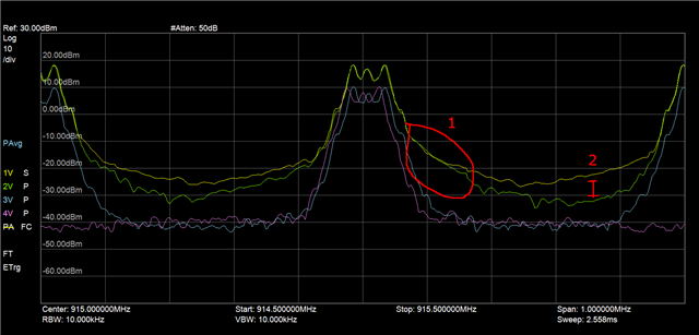
Fast forward and we discovered when using the Force VDDR option, the radio outputs quite a lot of in-channel noise on the high power path.  If we uncheck the Force VDDR option, the emission is a bit better (although, this radio is nowhere near as clean as CC1200).  Now, though, we are back to not getting full power on the low PA path.

How can we properly adjust the VDDR voltage and so-called "boost" mode in software at runtime to achieve optimal low power path performance (+14 dBm), while keeping Force VDDR unchecked to optimize emissions when using the high power PA path?  The documentation in the reference manual is vague and just says "Only to be used through TI provided API" ...so what API functions should I be looking for to handle VDDR voltage?

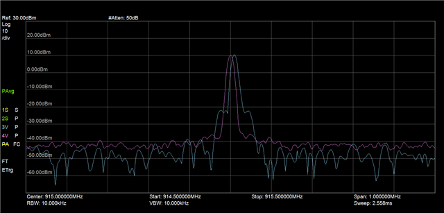
Another thing we noticed is CC1311P3 is generally much noisier (extra energy) on channel than CC1200.  Is this a known issue or is there some magic settings to clean up the emission?  We are basically using the similar modulation scheme based on Smart RF Studio 50kbps 2-GFSK setup, and there is just a lot more side-channel energy on the CC1311P3 even on the low-power path...and even on the LP-CC1311P3 driven by SmartRF Studio.

  • Hi David,

    could you share spectrum plots showing what you describe?

    1. Spectrum plot of 20 dBm path with force VDDR enabled.

    2. Spectrum plot of 20 dBm path with force VDDR disabled.

    3. Spectrum plot of 14 dBm path.

  • I am attaching the traces.  The extra noise is more pronounced when changing channels, and since this is a frequency hopping radio, I've loaded a test firmware which switches between channels every 20ms.  SmartRF Studio sweep function puts a lot of dead time between transmissions, so it doesn't show the noise well.

    Yellow = LP-CC1311P3 High PA w/ Force VDDR on

    Green = LP-CC1311P3 High PA w/ Force VDDR off

    Blue = LP-CC1311P3 Low Power w/ Force VDDR on

    Purple = Reference radio (our own CC1200 based design; I can't easily load a test software on it right now, but trust me that it doesn't have the extra energy/noise between channels that the LP-CC1311P3 High PA has).

    We noticed extra energy in the marked area 1 when changing channels.  This energy is less pronounced when doing a static channel test.  Also, note the gap at the marked area 2 when comparing the Force VDDR option.

    I have a portable analyzer at the moment and it's slow...I'll see if I can get even better traces showing in-channel energy from our big scope.

    Additionally for reference, you can also see extra noise on LP-CC1311P3 when comparing it to our reference CC1200 module.  You can see the extra wide "hips" about halfway down the carrier in the image below.

    Blue = LPCC1311-P3 CW mode (from SmartRF Studio)

    Purple = CC1200 based radio in CW mode.

    Maybe a followup question.  With the extra energy on the air with Force VDDR on while using the High PA path, would we expect to get less sensitivity?  

    Anyway, the documentation/examples say we shouldn't use Force VDDR On with the high power path...but I need 1 software to be able to switch between +20 and +14 dBm after bootup configured by the host board and I can't use 2 different CCFG configurations.  So if we shouldn't expect a reduction in sensitivity with Force VDDR On, maybe it is ok to run it that way in spite of the extra in-band energy?