This thread has been locked.

If you have a related question, please click the "Ask a related question" button in the top right corner. The newly created question will be automatically linked to this question.

CC2533EM-REFDES: Recommended decoupling capacitors

Part Number: CC2533EM-REFDES
Other Parts Discussed in Thread: CC2533

Some of our products are using the CC2533 for UHF communications. We found that that decoupling capacitors values differs from the specified in the CC2533EM-REFDES.

We have placed 1uF caps, it was choosen more than 10 years ago and we have no note/reason of why this choice. Looks more reasonable to place 100nF as you have in the REFDES.

CC2533EM-REFDES capacitors under discussion are connected to DVDD and AVDD (1uF, 5x 100nF and 220pF).


Our design, to be reviewed:
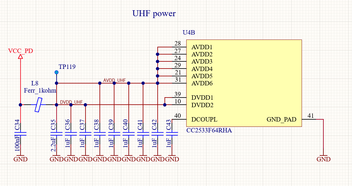
Design-UnderReview.png

Additionally, is L8 and other choices are ok as it is?

We would appreciate yor recommendation and review.

Thank you

  • L8: The spec of this will be dependent on the rest of the system. If you don't have any other noise sources, it could be that you don't need it, in some other cases it could be that you need to go through the system and find which frequencies that you need to attenuate.

    You existing design, does that pass ETSI/ FCC etc? If so, you probably don't have to change anything. Some of the decouplings could probably be removed, they are just added in the ref design as good design practice. But 100 nF most likely gives better decoupling. One way  to get a first indication is if you send a CW with the existing, look at the output with a spectrum (in TX), change the decouplings and do the same measurement. If you don't see any change on spurs etc you are probably fine. Note that change in decoupling will also change radiated performance coming from the board and not the antenna.