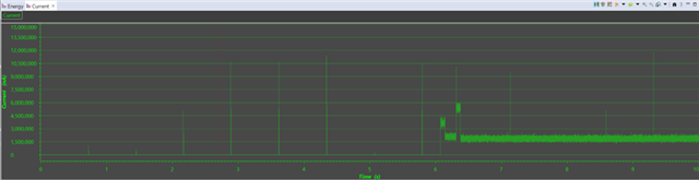
CC1312R: Power_idleFunc

Part Number: CC1312R

I am implementing standby mode using the following driver function in a no-RTOS environment:

Power_idleFunc();

--------------
    while( g_eventFlag == 0 && g_aonRtcEventFlag == 0 ){
        Power_idleFunc();
    }
-------------- Wake-up from standby is triggered by an external interrupt. However, even though no external interrupt occurs during standby, there is a period of about 3.5 hours where current consumption remains at 1 mA. The graph plots current consumption measured at 5-second intervals. No wake-up from standby occurs during this 1 mA period. It seems highly likely that something is happening inside Power_idleFunc(); do you have any ideas as to what this might be? Also, since Power_idleFunc(); cannot be used in this situation, is my only option to implement the low-power processing myself?
  • I have not been able to reproduce what you are observing.

    I took the rfWakeOnRadioTx example from the latest SDK, and modified it to simply stay in standby all the time, and just wake up and toggle a led every time a button is pushed.

    The modified example is shown below:

    /***** Includes *****/
    #include <stdlib.h>
    
    /* Drivers */
    #include <ti/drivers/Power.h>
    #include <ti/drivers/GPIO.h>
    
    #include <ti/devices/DeviceFamily.h>
    #include DeviceFamily_constructPath(driverlib/cpu.h)
    #include DeviceFamily_constructPath(driverlib/interrupt.h)
    
    /* Board Header files */
    #include "ti_drivers_config.h"
    
    /***** Defines *****/
    
    
    /***** Variable declarations *****/
    /* Button state */
    volatile bool buttonPushed = false;
    
    /***** Function definitions *****/
    /* GPIO interrupt Callback function for CONFIG_GPIO_BTN1. */
    void buttonCallbackFunction(uint_least8_t index)
    {
        /* Simple debounce logic, only toggle if the button is still pushed (low) */
        CPUdelay((uint32_t)((48000000/3)*0.050f));
        if (!GPIO_read(index)) {
            /* Post TX semaphore to TX task */
            bool previousHwiState = IntMasterDisable();
            // Tricky IntMasterDisable():
            //true  : Interrupts were already disabled when the function was called.
            //false : Interrupts were enabled and are now disabled.
            buttonPushed = true;
            if (!previousHwiState) {
                IntMasterEnable();
            }
        }
    }
    
    
    /* Main thread function. Enters standby and wakes on button push. */
    void *mainThread(void *arg0)
    {
        GPIO_setConfig(CONFIG_GPIO_GLED, GPIO_CFG_OUT_STD | GPIO_CFG_OUT_LOW);
        GPIO_setConfig(CONFIG_GPIO_BTN1, GPIO_CFG_IN_PU | GPIO_CFG_IN_INT_FALLING);
    
        /* Install Button callback */
        GPIO_setCallback(CONFIG_GPIO_BTN1, buttonCallbackFunction);
    
        /* Enable interrupts */
        GPIO_enableInt(CONFIG_GPIO_BTN1);
    
        /* Enter main loop */
        while(1)
        {
            /* Wait for a button press */
            bool previousHwiState = IntMasterDisable();
            while (buttonPushed == false) {
                IntMasterEnable();
                Power_idleFunc();
                IntMasterDisable();
            }
            buttonPushed = false;
            if (!previousHwiState) {
                IntMasterEnable();
            }
    
            /* Button was pressed, toggle LED and return to standby */
            GPIO_toggle(CONFIG_GPIO_GLED);
        }
    }

    Not sure what HW you are running on, but how can you be sure that there have been no glitches etc. on the GPIO you have used to wake up your device from standby.

    Please try the example above and see if you have any troubles with this.

    BR

    Siri

  • I am basing my work on that sample.
    Regarding the fact that you were unable to verify the issue:
    Did you perform a test where the device was left in standby mode for approximately 45 hours without pressing any buttons?
    The graph I posted earlier shows that there are moments when a 1mA current is drawn, even while the device remains in standby.
    Is the device not designed to maintain a standby state for such a duration?
    
    
  • No, I did not run the test for 45 hours, but the code example I used have been out on the web for several years and we have never gotten any feedback that the device wakes up from standby on its own, while waiting for a pin interrupt.

    I also do not understand you comment saying that the device draws 1 ma even if it remains in Standby. If the device draws 1 mA, it is not in Standby.To debug your issue you should make a simple code example that does nothing other than being in Standby, waking up on GPIO interrupt, and returning immediately to Standby.

    The code you are testing with is obviously doing something other than this, as it remains in IDLE for several hours (what makes it go back to Standby?)

    To figure out if the radio is somehow being reset etc, you could do something like this:

    volatile bool buttonPushed = false;
    
    void buttonCallbackFunction(uint_least8_t index)
    {
        CPUdelay((uint32_t)((48000000/3)*0.050f));
        if (!GPIO_read(index))
        {
            bool previousHwiState = IntMasterDisable();
    
            buttonPushed = true;
    
            uint8_t i;
    
            for (i = 0; i < 10; i++)
            {
                GPIO_toggle(CONFIG_GPIO_RLED);
                CPUdelay((uint32_t)((48000000/3)*0.050f));
            }
    
            if (!previousHwiState)
            {
                IntMasterEnable();
            }
        }
    }
    
    void *mainThread(void *arg0)
    {
        PowerCC26X2_ResetReason resetReason = PowerCC26X2_getResetReason();
    
        // Device booted due to power on reset
        if (resetReason == PowerCC26X2_RESET_POR)
        {
            // Do not hang. This is the only reset reason that should happen
            // when powering up the system
            uint8_t i;
    
            for (i = 0; i < 10; i++)
            {
                // Make sure the RED LED is toggling when powering up the system 
                // and starting the test
                GPIO_toggle(CONFIG_GPIO_RLED); 
                CPUdelay((uint32_t)((48000000/3)*0.050f));
            }
    
        }
    
        // Device reset due to clock loss
        if (resetReason == PowerCC26X2_RESET_CLK)
        {
            while(1)
            {
                GPIO_toggle(CONFIG_GPIO_GLED);
                CPUdelay((uint32_t)((48000000/4)*0.5f));
            }
        }
    
        // Device reset due to VDDR brownout event
        if (resetReason == PowerCC26X2_RESET_VDDR)
        {
            while(1)
            {
                GPIO_toggle(CONFIG_GPIO_GLED);
                CPUdelay((uint32_t)((48000000/4)*1.0f));
            }
        }
    
        //Device reset due to VDDS brownout event
        if (resetReason == PowerCC26X2_RESET_VDDS)
        {
            while(1)
            {
                GPIO_toggle(CONFIG_GPIO_GLED);
                CPUdelay((uint32_t)((48000000/4)*1.5f));
            }
        }
    
        // Device reset due to pin reset
        if (resetReason == PowerCC26X2_RESET_PIN)
        {
            while(1)
            {
                GPIO_toggle(CONFIG_GPIO_GLED);
                CPUdelay((uint32_t)((48000000/4)*2.0f)); // This will trigger if there are some glitches etc. when powering up the board
                                                         // So make sure it does not go here when test is started
            }
        }
    
        // Device woke up from noise on the JTAG TCK line
        if (resetReason == PowerCC26X2_RESET_TCK_NOISE)
        {
            while(1)
            {
                GPIO_toggle(CONFIG_GPIO_GLED);
                CPUdelay((uint32_t)((48000000/4)*2.5f));
            }
        }
    
        // Device reset triggered by software or watchdog timeout
        if (resetReason == PowerCC26X2_RESET_SYSTEM)
        {
            while(1)
            {
                GPIO_toggle(CONFIG_GPIO_GLED);
                CPUdelay((uint32_t)((48000000/4)*3.0f));
            }
        }
    
        // Device woke up due to warm reset event. Usually debugger related.
        if (resetReason == PowerCC26X2_RESET_WARM_RESET)
        {
            while(1)
            {
                GPIO_toggle(CONFIG_GPIO_GLED);
                CPUdelay((uint32_t)((48000000/4)*3.5f));
            }
        }
    
        // Enable pin interrupt for waking the device from Standby
        GPIO_setConfig(CONFIG_GPIO_BTN1, GPIO_CFG_IN_PU | GPIO_CFG_IN_INT_FALLING);
        GPIO_setCallback(CONFIG_GPIO_BTN1, buttonCallbackFunction);
        GPIO_enableInt(CONFIG_GPIO_BTN1);
    
        while(1)
        {
            bool previousHwiState = IntMasterDisable();
            while (buttonPushed == false)
            {
                IntMasterEnable();
                Power_idleFunc();
                IntMasterDisable();
            }
            buttonPushed = false;
            if (!previousHwiState)
            {
                IntMasterEnable();
            }
        }
    }

    Make sure that you enter the resetReason = PowerCC26X2_RESET_POR when powering up the board and starting your test (power on and off until you start in the correct state). After that you leave the test alone, with only a logic analyzer connected to the GPIO that can wake the device, or to the LED toggling in the callback.

    The logic analyzer should be set to trigger on this pin.

    This will tell you if there has been any noise on this pin waking up the device.

    If the board for other reasons experience a reset, the toggling rate in the different while loops will tell you what has happened.

    BR

    Siri

  • Since this phenomenon came to light, I have thoroughly investigated whether a reset occurred or if the system woke up from standby mode.
    As you suggested, I suspect that some form of noise is triggering a pin interrupt.
    Regarding the system state, however, it did not wake up from standby, nor did a reset occur.
    I agree that it is baffling for the device to consume 1mA of current while in standby mode; however, the fact is that this is actually happening, which is why it is a problem.
    Could you clarify what you mean by the device remaining in an "IDLE" state for several hours during testing?
    Does "idle state" equate to a 1mA draw? Regarding the transition back to standby mode—while the event itself is time-based—I do not know the underlying cause, and therefore I do not know how to address it.
    
    
    The application operates as follows: upon startup, it performs wireless communication and then waits in standby mode; subsequently, it wakes from standby triggered by pin interrupts or AON_RTC interrupts to sample data and transmit it wirelessly, returning to standby once transmission is complete.
    Since the timing of the 1mA current draw does not coincide with the transition from wake-up back to standby, the issue likely lies within `Power_idleFunc()`.
    Additionally—though I am unsure if this provides a clue—if I manually trigger a pin interrupt while the 1mA current is flowing, the application proceeds normally; however, even though the process of returning to standby executes as expected, the 1mA current persists. This 1mA current continues for a certain period before eventually returning to normal on its own.
    
    
    I have developed applications using the MSP430 series that utilize LPM for low-power operation, so I have never encountered a phenomenon like this before; I have been struggling to understand it for over three months now.
     
  • How do you know that some kind of reset did not find place, and how do you know that the device is in standby when it draws 1 mA?

    I looked throug the data sheet, and the IDLE current consumption is around 590 uA, and not 1 mA as I assumed.

    If you device is indeed in standby and are drawing 1 mA current, there must be something connected to some of your IOs that are causing this current draw.

    For example, If I run som code that first is in standby with the LED off, and then turns it ON, and go back to standby, you will see that the current draw goes up from sub 1 uA to about 1.85 mA. The device is still in standby (you can confirm that by the recharge pulses that only happens in Standby), but the LED is drawing a lot of current.

    The first thing you should do it to make sure that there are recharge pulses present when you see the 1 mA current draw.

    If you see the re-charge pulses, you are in standby and need to figure out what is drawing the current on your HW (If you have peripherals connected to your board, disconnect the physically, and simplify your code to not access them)

    I will be surprised if the problem is in the power driver, as you state, as that driver is used across many of our device platforms for years without having seen issues like this.

    If we shall be able to dig into this further, you will need to provide us with some code that runs on our launchpads and illustrates this error.

    Both me and colleague have been running test on this since last morning and have not been able to reproduce it.

    Without having anything that fails on our end, I am not sure how we can proceed.

    Siri

  • Debug logs are output to the UART upon reset, as well as when waking up from standby mode.
    An ammeter is permanently connected; since wireless communication occurs upon wake-up via pin interrupt—causing current to flow—I can distinguish the differences in operation.
    I naturally suspected the I/O pins as well, but found no issues there.
    As shown in the graph I provided earlier, the 1mA current draw persists for approximately 3.5 hours.
    No logs are output during this period, either.
    Having run out of alternative ideas on my end, I plan to use the source code you provided yesterday to test a simple implementation on the LaunchPad.
    I will let you know the results once I have them.
    
    
  • I am writing to report that the same phenomenon (1mA current draw) occurred on the evaluation board.
    I am attaching the waveforms and source code.
    Here are the details of the tests performed and their results:
    test1: Wake-up from standby using only the button → Remained in standby for 69 hours; no issues with current consumption.
    test2: test1 conditions + added Timer and RF transmission processing during active mode → Remained in standby for 69 hours; no issues with current consumption.
    test3: test2 conditions + added SPI and UART processing during active mode → Remained in standby for 69 hours; no issues with current consumption.
    test4: test3 conditions + added processing to wake up every 5 minutes using AON_RTC → Over the 69-hour period, the device cycled between 9 hours of standby and 3 hours of 0.8mA consumption (issue with current consumption observed).
    
    Based on these results, it appears that the use of AON_RTC triggered the 1mA current issue.
    I am providing the source code; could you please review the test setup on the evaluation board and the source code itself, and share your insights?

    sleepTest4.zip

  • I have not the opprtunity to let this run for 10s of hours to wait for it to possible fail and try to figure out what is going on.

    From you description everything works well when you are just using our different drivers, and the problems starts when you start using the aon_rtc, which we do not provide a driver for (only driverlib). Driverlig is not meant to be used by the application, but is a layer that is being used by the drivers, and then the application should use the drivers.


    I asked my friend claude if there might be any issues with your code with respect to using the aon_rtc, and here is what came back:

    "

    Based on my analysis, I've found several critical issues that could cause excessive current consumption after hours:

    Critical Issues:

    1. Interrupt handler registered multiple times (line 380) — Every time AonRtcSetInterval() is called, IntRegister() and IntEnable() are called again, but there's no corresponding IntUnregister() or IntDisable() before re-registering. After several hours of sleep/wake cycles, this could cause handler conflicts or stuck interrupts.
    2. Interrupt handler contains a busy loop with GPIO toggling (lines 263-275) — The AonRTC_InterruptHandler() has debug code that:

        - Toggles LED 10 times with delays (CPUdelay)

        - Disables/re-enables interrupts manually

        - This runs every time the RTC fires — blocks interrupts and wastes energy

    1. Missing interrupt cleanup in SleepSystem() — The SleepSystem() function closes peripherals but never disables the AON_RTC interrupt before sleeping. If the interrupt fires during sleep setup, it could prevent proper power-down or cause the oscillator to stay active.
    2. No protection against handler re-entry — The handler modifies g_aonRtcEventFlag without checking if it's already been called, and there's no debouncing logic

    "

    Siri

  • Thank you for your response. I have a few follow-up questions regarding the information you provided; could you please review them? This phenomenon has been verified on the CC1312 evaluation board; are there no plans to investigate reports of this nature? The issue begins to manifest approximately nine hours after power-on. Since it occurs simply by leaving the device running with an ammeter connected, I believe it would be prudent to investigate the root cause—what are your thoughts on this? Does this mean that the `aon_rtc` function should not be used directly by the application? I understand the design intends for the application to utilize it via the driver, but how exactly is it used through the driver? In this specific application, the requirement is for a function that triggers a wakeup if no external input interrupt occurs within a certain period.
    1. Understood; however, the AonRtc function did not malfunction when 1 mA was generated.
    2. This processing was included to verify whether an interrupt occurs in AonRtc, so in reality, it does not trigger.
    3. I have not disabled the AON_RTC interrupt. Regarding the timing "before entering sleep," do you mean I should enable it immediately before `Power_idleFunc` is called? Since this implies a risk of preventing proper power-down or causing the oscillator to keep running, are there any ways to investigate this? Is analyzing the `Power_sleep` function the only option?
    4. No interrupt re-entry is occurring with the AonRTC; this has been confirmed via UART logs. As previously reported, the waveforms show that no external interrupts are occurring, while the AonRTC interrupt continues to operate at 5-minute intervals. Since the waveform sampling interval is 5 seconds, we are capturing very few samples during the Active state; however, the issue lies in the sustained 1 mA current draw (e.g., 2.93h, 2.89h), compared to 0.8 mA on the evaluation board.

  • If you want us to investigate this further, you need to provide an easier way for us to reproduce this issue.

    You suspect that the problem is related to the AON_RTC, meaning that you should try to make a VERY simple example were you simply use the AON_RTC to wake up the device at a given interval. You should try to decrease this interval to see if it can trigger it to fail sooner.

    Siri

  • /*
     * Copyright (c) 2017-2022, Texas Instruments Incorporated
     * All rights reserved.
     *
     * Redistribution and use in source and binary forms, with or without
     * modification, are permitted provided that the following conditions
     * are met:
     *
     * *  Redistributions of source code must retain the above copyright
     *    notice, this list of conditions and the following disclaimer.
     *
     * *  Redistributions in binary form must reproduce the above copyright
     *    notice, this list of conditions and the following disclaimer in the
     *    documentation and/or other materials provided with the distribution.
     *
     * *  Neither the name of Texas Instruments Incorporated nor the names of
     *    its contributors may be used to endorse or promote products derived
     *    from this software without specific prior written permission.
     *
     * THIS SOFTWARE IS PROVIDED BY THE COPYRIGHT HOLDERS AND CONTRIBUTORS "AS IS"
     * AND ANY EXPRESS OR IMPLIED WARRANTIES, INCLUDING, BUT NOT LIMITED TO,
     * THE IMPLIED WARRANTIES OF MERCHANTABILITY AND FITNESS FOR A PARTICULAR
     * PURPOSE ARE DISCLAIMED. IN NO EVENT SHALL THE COPYRIGHT OWNER OR
     * CONTRIBUTORS BE LIABLE FOR ANY DIRECT, INDIRECT, INCIDENTAL, SPECIAL,
     * EXEMPLARY, OR CONSEQUENTIAL DAMAGES (INCLUDING, BUT NOT LIMITED TO,
     * PROCUREMENT OF SUBSTITUTE GOODS OR SERVICES; LOSS OF USE, DATA, OR PROFITS;
     * OR BUSINESS INTERRUPTION) HOWEVER CAUSED AND ON ANY THEORY OF LIABILITY,
     * WHETHER IN CONTRACT, STRICT LIABILITY, OR TORT (INCLUDING NEGLIGENCE OR
     * OTHERWISE) ARISING IN ANY WAY OUT OF THE USE OF THIS SOFTWARE,
     * EVEN IF ADVISED OF THE POSSIBILITY OF SUCH DAMAGE.
     */
    /*
     *  ======== PowerCC26X2_nortos.c ========
     */
    
    #include <stdio.h>
    #include <stdlib.h>
    
    #include <ti/drivers/ITM.h>
    #include <ti/drivers/Power.h>
    #include <ti/drivers/power/PowerCC26X2.h>
    #include <ti/drivers/power/PowerCC26X2_helpers.h>
    
    #include <ti/drivers/dpl/ClockP.h>
    #include <ti/drivers/dpl/HwiP.h>
    #include <ti/drivers/dpl/SwiP.h>
    
    #include <ti/devices/DeviceFamily.h>
    #include DeviceFamily_constructPath(inc/hw_types.h)
    #include DeviceFamily_constructPath(driverlib/prcm.h)
    #include DeviceFamily_constructPath(driverlib/osc.h)
    #include DeviceFamily_constructPath(driverlib/cpu.h)
    #include DeviceFamily_constructPath(driverlib/sys_ctrl.h)
    #include DeviceFamily_constructPath(driverlib/vims.h)
    
    extern PowerCC26X2_ModuleState PowerCC26X2_module;
    
    extern uint32_t ClockP_tickPeriod;
    
    static uintptr_t PowerCC26X2_swiKey;
    
    /*
     *  ======== PowerCC26XX_standbyPolicy ========
     */
    void PowerCC26XX_standbyPolicy(void)
    {
        bool justIdle = true;
        uint32_t constraints;
        uint32_t ticks, time;
        uintptr_t key;
    
        /* disable interrupts */
        key = HwiP_disable();
    
        /*
         * Check if the Power policy has been disabled since we last checked.
         * Since we're in this policy function already, the policy must have
         * been enabled (with a valid policyFxn) when we were called, but
         * could have been disbled to short-circuit this function.
         * SemaphoreP_post() does this purposely (see comments in there).
         */
        if (!PowerCC26X2_module.enablePolicy)
        {
            HwiP_restore(key);
    
            return;
        }
    
        /* check operating conditions, optimally choose DCDC versus GLDO */
        PowerCC26X2_sysCtrlUpdateVoltageRegulator();
    
        /* query the declared constraints */
        constraints = Power_getConstraintMask();
    
        /* do quick check to see if only WFI allowed; if yes, do it now */
        if ((constraints & ((1 << PowerCC26XX_DISALLOW_STANDBY) | (1 << PowerCC26XX_DISALLOW_IDLE))) ==
            ((1 << PowerCC26XX_DISALLOW_STANDBY) | (1 << PowerCC26XX_DISALLOW_IDLE)))
        {
    
            /* Flush any remaining log messages in the ITM */
            ITM_flush();
            PRCMSleep();
            /* Restore ITM settings */
            ITM_restore();
        }
        /*
         *  check if any sleep modes are allowed for automatic activation
         */
        else
        {
            /* check if we are allowed to go to standby */
            if ((constraints & (1 << PowerCC26XX_DISALLOW_STANDBY)) == 0)
            {
                /*
                 * Check how many ticks until the next scheduled wakeup.  A value of
                 * zero indicates a wakeup will occur as the current Clock tick
                 * period expires; a very large value indicates a very large number
                 * of Clock tick periods will occur before the next scheduled
                 * wakeup.
                 */
                ticks = ClockP_getTicksUntilInterrupt();
    
                /* convert ticks to usec */
                time = ticks * ClockP_tickPeriod;
    
                /* check if can go to STANDBY */
                if (time > Power_getTransitionLatency(PowerCC26XX_STANDBY, Power_TOTAL))
                {
    
                    /* schedule the wakeup event */
                    ticks -= PowerCC26X2_WAKEDELAYSTANDBY / ClockP_tickPeriod;
                    ClockP_setTimeout(ClockP_handle((ClockP_Struct *)&PowerCC26X2_module.clockObj), ticks);
                    ClockP_start(ClockP_handle((ClockP_Struct *)&PowerCC26X2_module.clockObj));
    
                    /* Flush any remaining log messages in the ITM */
                    ITM_flush();
    
                    /* go to standby mode */
                    Power_sleep(PowerCC26XX_STANDBY);
    
                    /* Restore ITM settings */
                    ITM_restore();
    
                    ClockP_stop(ClockP_handle((ClockP_Struct *)&PowerCC26X2_module.clockObj));
                    justIdle = false;
                }
            }
    
            /* idle if allowed */
            if (justIdle)
            {
    
                /* Flush any remaining log messages in the ITM */
                ITM_flush();
    
                /*
                 * Power off the CPU domain; VIMS will power down if SYSBUS is
                 * powered down, and SYSBUS will power down if there are no
                 * dependencies
                 * NOTE: if radio driver is active it must force SYSBUS enable to
                 * allow access to the bus and SRAM
                 */
                if ((constraints & (1 << PowerCC26XX_DISALLOW_IDLE)) == 0)
                {
                    uint32_t modeVIMS;
                    /* 1. Get the current VIMS mode */
                    do
                    {
                        modeVIMS = VIMSModeGet(VIMS_BASE);
                    } while (modeVIMS == VIMS_MODE_CHANGING);
    
                    /* 2. Configure flash to remain on in IDLE or not and keep
                     *    VIMS powered on if it is configured as GPRAM
                     * 3. Always keep cache retention ON in IDLE
                     * 4. Turn off the CPU power domain
                     * 5. Ensure any possible outstanding AON writes complete
                     * 6. Enter IDLE
                     */
                    if ((constraints & (1 << PowerCC26XX_NEED_FLASH_IN_IDLE)) || (modeVIMS == VIMS_MODE_DISABLED))
                    {
                        PowerCC26X2_sysCtrlIdle(VIMS_ON_BUS_ON_MODE);
                    }
                    else
                    {
                        PowerCC26X2_sysCtrlIdle(VIMS_ON_CPU_ON_MODE);
                    }
    
                    /* 7. Make sure MCU and AON are in sync after wakeup */
                    SysCtrlAonUpdate();
                }
                else
                {
                    PRCMSleep();
                }
    
                /* Restore ITM settings */
                ITM_restore();
            }
        }
    
        /* re-enable interrupts */
        HwiP_restore(key);
    }
    
    /*
     *  ======== PowerCC26XX_schedulerDisable ========
     */
    void PowerCC26XX_schedulerDisable(void)
    {
        PowerCC26X2_swiKey = SwiP_disable();
    }
    
    /*
     *  ======== PowerCC26XX_schedulerRestore ========
     */
    void PowerCC26XX_schedulerRestore(void)
    {
        SwiP_restore(PowerCC26X2_swiKey);
    }
    

    I have figured out the logic behind the "9 hours = ultra-low current consumption" and "approx. 3 hours = 1mA current draw" behavior. When low-power operation is active, the function `void PowerCC26XX_standbyPolicy(void)`—found in the attached `PowerCC26X2_nortos.c` file—is presumably being called. It turns out that a situation was occurring where the condition on line 127— `if (time > Power_getTransitionLatency(PowerCC26XX_STANDBY, Power_TOTAL))` —was not met, preventing the transition to `Power_sleep(PowerCC26XX_STANDBY);` on line 139. In this case, the system remained in "Idle mode," which I believe accounts for the 1mA current draw. This state persisted for approximately 3 hours. During the 9-hour period, the condition was met, and `Power_sleep(PowerCC26XX_STANDBY);` was successfully called. So, I have a question: How should I modify the implementation to ensure the system always transitions to `Power_sleep(PowerCC26XX_STANDBY);`? Should I create a custom policy that operates independently of the scheduler, using `PowerCC26XX_standbyPolicy` as a reference?

  • The Power_getTransitionLatency function reports the minimal hardware transition latency for a specific sleep state. 

    The power driver uses this function to determine if there is time to go to standby or not.

    If you do not enter standby, but IDLE instead, that simply means that there is something in your application that is scheduled in the near future, and that you have not time to enter Standby before this is to happen, and the device enters idle instead.

    The current consumption in IDLE is less that 0.6 mA, so that does not add up with the 1 mA you measure.

    We do not recommend anyone to start modifying the power driver, and have no recommendations as to how you can do this.

    Siri

  • Subsequent debugging revealed that on the evaluation board, `Power_getTransitionLatency` returns 0 at the moment the current drops to 0.8 mA. What does this signify? What is the reference basis for the duration measured by `Power_getTransitionLatency`? Since this is a noRTOS application, is it necessary for `Power_getTransitionLatency` to account for tasks scheduled to occur in the near future? Also, the system was entering the idle state via `PowerCC26X2_sysCtrlIdle(VIMS_ON_CPU_ON_MODE);`. The discrepancy regarding the 1 mA figure is due to the difference in circuit boards; the evaluation board draws 0.8 mA. The phenomenon should occur if the device is left running for nine hours after startup. Since I have provided the source code, could you please verify the issue and explain the underlying mechanism?