This thread has been locked.

If you have a related question, please click the "Ask a related question" button in the top right corner. The newly created question will be automatically linked to this question.

Wireless Communication with CC110L Air Module

Other Parts Discussed in Thread: CC110L, MSP430G2553, SIMPLICITI

Hi, I am using the MSP430 Launchpad along with the CC110L Air Module for a wireless RF communication. I've been working on this for a few days and all the forms/tutorials I've read all say that using the Air Module is utterly complicated. I was hoping to be able to start small with a simple communication that turns an LED on on Launchpad A if a button is pushed on Launchpad B. I am using Grace (a godsend) to set up all the back end so all I need help with is the actual communication.

The setup is 4-wire with P1.4 for the clock, P1.1 for SOMI, P1.2 for SIMO, STE active high, MSB first, 5000 bps, and I also had Grace set up interrupt handlers for both receive and transmit. I can't imagine that setting up a simple communication would be more than 40-50 lines of code but I may be wrong here (this is my first time dealing with SPI and RF communications). I'm not sure how to get the two Air Modules to sync (or how to choose one certain slave out of many to talk to) and I'm having trouble figuring out how to send any actual data and receive on the other side.

Any help would be great. Thanks so much in advance.

-Richmund

  • Hi Richmund

    3146.cc110L_easy_link_msp_exp430g2.zip

    Here is a code example for a easy one way link between two Launchpads with the CC110L Air module. The code continiuously sends 30 bytes packets with random data from the transmitter on button push. On the receiving side the receiver toggles the red led if it has received a packet with good CRC.

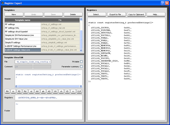
    Different register settings kan be directly exported from SmartRF Studio abd pasted into the code.If you have a CC110L Development Kit you can send packets between SmartRF Studio and the Launchpad.

    The code assumes you are using the MSP430G2553 that is included in the boosterpack.

    Hope this is will help you on the way. Please do not hesitate if you have any questions regarding the SW.

  • Hi Martin,

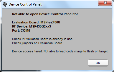
    Thank you very much for your response. I downloaded the code you suggested and saw that it was built for the IAR Workbench so I opened it using that program but when I tried to compile there were errors and I couldn't get it to run correctly. I then looked at SmartRF (again from your previous response) and tried to configure the devices but that also failed. First, SmartRF found the devices but did not recognize the transceiver, then when I tried double clicking on the device to configure it, I get this error:

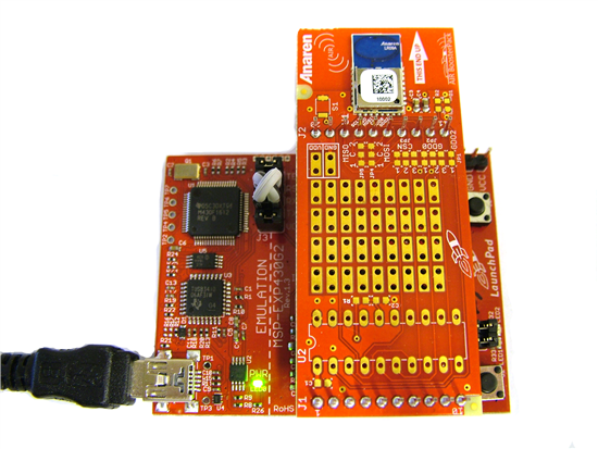
    The RX and TX Jumpers are rotated 90 degrees so that they're running parallel with the Air Module. The Air Module is lined up on the Launchpad such that the two space ships are facing the same way. I think that's all that needs to be done. I also tried replacing the RX/TX Jumpers with the cross jumpers that came with the Air Module and the same problem appeared. The ATC BoosterStack Lite GUI can't seem to find them either.

    Thanks,

    Richmund

  • Are there any simple step-by-step tutorials out there for the CC110L Air Module integration with the MSP430G2553 Launchpad?

  • Hi Richmund

    I saw that there was some debug configurations that I had not removed. Posting the new code that only have the TX and RX configuration. The code will be built, downloaded and debugged with IAR without any errors. What version of IAR are you using? The project was built with IAR version 5.40 for MSP.

    2318.cc110L_easy_link_msp_exp430g2.zip

    I'm sorry if I was unclear in the previous post, but you can't program or control the Launchpad with SmartRF Studio. What I tried to tell you is that you can use SmartRF Studio to find your register settings (e.g. change data rate, modulation etc) and then export the register settings into the code (cc11xL_easy_link_msp_exp_430g2_reg_config.h ) using the register export function.

    Depending on which revision you have of the launchpad you need to use the cross jumpers for the RXD and TXD pins. I have used version 1.4 of the launchpad and this need the cross jumpers (see picture below). I know that for newer versions of the board this is fixed so you don't need the cross jumpers, but I do not know from which version.

  • Martin! It WORKS!!

    You are a godsend. I've been working just to get a small communication for weeks. Hours every day. You have no idea how happy this makes me. But it's not over yet, now I want to learn your code to import the concepts into my code. I may have more questions down the line if you don't mind. But this is an excellent start. The code seems fairly straight forward and does exactly what I'm looking for.

    A million Thank Yous.

  • Hi all, I just got a couple of CC110L booster packs too and would like a SIMPLE example of something that works... So I found this thread but I can't really seem to make it work!

    I am using CCS 5.3 so I can't import the code directly, since it is for IAR, right?

    I tried looking at the example provided with the boosterpacks but it is really over complicated for what I want to do; send and receive simple packages (a few bytes a couple of times per minute). I also tried setting up SimpliciTi (following a tutorial) but couldn't get that to work either. I would really just like a very simple example of sending and receiving simple data for this radio module!

    Any hints? :)

  • Hi Brian

    Look at the answer I gave you in the following post:

    http://e2e.ti.com/support/low_power_rf/f/155/p/251144/894975.aspx#894975


  • Hi Martin,

    I want to send character M from PC to MSP1 serially and to turn on the led connected with PORT2 BIT0 on MSP2 via air booster. But i couldn’t do that. Can you help me or give me an sample code?

  • Quick question regarding the red LED driving by this sample program.  On the MSP430 launchpad, the LED is connected to Port 1.0 of the processor, which is also tied to the GDO2 pin of the radio module.

    From what I can tell, the radio is being configured to provide the CHIP_RDYn signal on the GDO2 output (based on the fact that the default value of 0x29 for this radio control register is not being modified by the code).

    How are the LED drive from the processor and the CHIP_RDYn signal from the radio module not coming into conflict?  As best I can tell, the CHIP_RDYn signal is not being driven (if I disable the LED drive from the processor), but I'm not sure why.

  • Hi Kelly

    You are completely right. The LED1 is connected to P1.0 which is the same pin as the GDO2 pin from the CC110L is connected to. So there is a conflict here, and the GDO2 signal should be tri-stated when driving the LED1 from the MCU. I will be sure to change this in the example code.

  • yiğit remzi unat said:

    Hi Martin,

    I want to send character M from PC to MSP1 serially and to turn on the led connected with PORT2 BIT0 on MSP2 via air booster. But i couldn’t do that. Can you help me or give me an sample code?

    This is no problem. If you search the MSP forum you will find examples on how to set up UART for the MSP. Then you can program the MCU to send a packet every time it receives an M character over UART.

    Unfortunately I do not have the time to make an own example code for you, but with the easylink example code and UART examples from the MSP it is just a matter of combining the code examples into one application.

    Link to UART code examples for the MSP430G2553:

    http://www.ti.com/litv/zip/slac485c

  • Hi!

    If I want to send a number, what should i do?

  • Hi Valentin

    Could you elaborate on what you are trying to do? The packet format for the CC110L is described in the user's guide which can be found here:

    http://www.ti.com/product/cc110L


  • I want to connect an accelerometer to a module and then send the data from the accelerometer to the other one module(to control a robot).

  • Hi Valentin

    If you are planning to use the Launchpad with the air module, the easylink code I posed in the beginning of the thread can be used for the RF link. Just put your accelerometer data in the payload of the packet.

  • Hi,

    I am doing my project with the MSP430 .I am looking for the same topic. Is it possible to post the same code in ccs.I was stuck with that code.please help me...

    Thankyou.......

  • Hi,
    I am doing Bio medical sensor project.I was stuck with some code in ccs. Actually i am working with MSP430 launchpad along with cc110l air booster for wireless RF communication. I want to transfer data between these modules using a button push.i am looking for a code in ccs.

    Thankyou ........

    Best regards,
    Tejaswi
  • You can either convert the IAR project to CCS as Martin suggested in a previous post (e2e.ti.com/.../894975) and/ or look at the easylink for CCS here: processors.wiki.ti.com/.../Category:Sub-1GHz. Based on these you should get your project up and running.
  • Hello ,

                    Thankyou...

    Best regards,

    T.Tejaswi