This thread has been locked.

If you have a related question, please click the "Ask a related question" button in the top right corner. The newly created question will be automatically linked to this question.

Problem with CC430F6137 PCB

Other Parts Discussed in Thread: CC1101, CC430F6137

Hi Eveyone

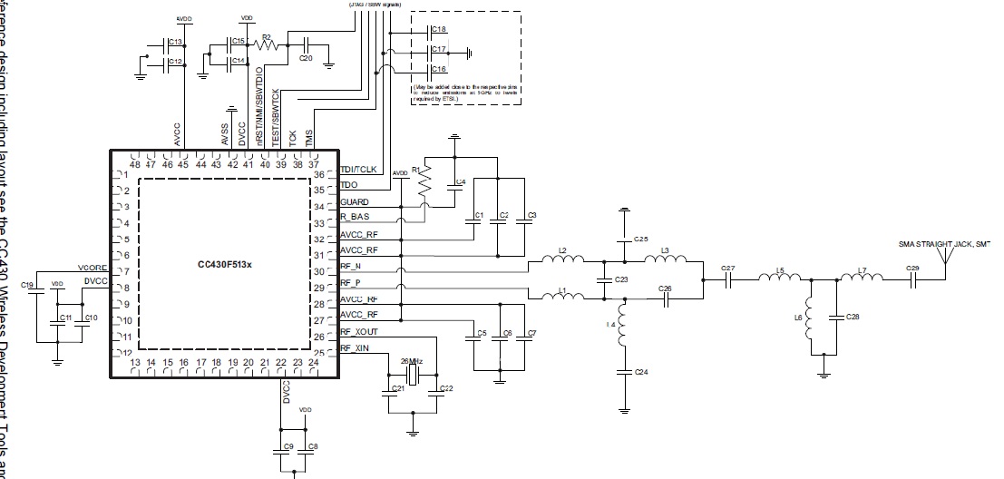
I am student and doing a student Project. So for my project I made a two layer PCB Board for CC430F6137. I can program it well using JTAG 2 SPY Interface. For Blinking LED, this PCB board work well. But when I run the code for transmitting some data using inbuilt RF CC1101, it doesn't work. But same code work for eZ430-Chronos Development Kit for 433 MHz.

I also notice one problem with this PCB, when I burn code using JTAG Interface (Blinking Led Using Timer A), It works. But after powering Off and then powering on again, It wont work. So please anyone can suggest me, what can be possible cause for this problem. What can I do next for getting my PCB working. I will be very thankful to them. I need it to working for completing my project. Please suggest me some idea.

Thanks and Regard

Vivek Kumar

  • Vivek, 

    Can you post your schematics, it sounds to me like you are missing something in the reset circuit or maybe you power supply is not high enough.

    Have you tried measuring all the voltages for all the supply pins on the device?

    Regards,
    Thomas 

  • 5305.CC430F6137_430MHZ.sch

    Thanks Thomas

    I have inserted the schematics file . I made it in Eagle. For making this I strictly follow the the application circuit given in CC430F6137.pdf.

    I will be very thankful to you for your help.

  • can you post a PDF version of the schematic, it show up very funny (hard to read) on my screen.

    /TA

  • Hi Thomas

    Thanks For your Help..

    Here I am attaching PDF version of my schematics and Image of circuit given in CC430F6137.pdf, that I followed for making this schematics.

    Some pin is shown open in PDF but it is connected to either ports of CC430F6137 or GND, depending on requirement. 

    Thanks

    Vivek

    7750.CC430F6137_1.pdf1805.CC430F6137_2.pdf

  • Hi Thomas

    Thanks for your help. I got reset part working fine.

    But still facing problem with RF part. My code for transmitting data from RF works with eZ430-Chrono for 433Mhz. But It is not working with the PCB I made. I am getting the Interrupt for end of package (with TX ) correctly but I am not getting data transmitted.

    Can you please check my RF circuit part. It will be very helpful for me..

    Thanks & Regard

    Vivek

  • Vivik, 

    Initially the most critical item to check when making you own board is the XTAL frequency. The frequency needs to be correct, that is with +/-20 parts per million or +/-500 hz at 26MHz. Depending on what test hardware you have available there are various methods of checking this.

    A RF spectrum analyzer is the easiest. The RF PLL will multiply the XTAL frequency up to say 915MHz and you can use a spectrum analyzer to check how much the carrier frequency is off. If you do not have a spectrum analyzer you can use some TI development kits and SmartRF studio and sweeps the band for RSSI and manually make a plot of where the center frequency is.

    I believe this is the root cause of what you are experiencing. If they are off enough the transmitter will be outside the receive bandwidth filter of the reciever and nothing will work.

    Regards,
    /TA 

  • HI Thomas

    Thanks For Your help. I will check this.

    But can you check the circuit I have attached before and confirm me that It will work for 433MHz. Because in the schematic of eZ430-Chronos, I found some different circuit for RF part.

    Thanks And Regard

    Vivek

  • hi.

    this is adi here, im a student and im doing my thesis on wireless sensors network. i want to develop a wearable patient monitoring device, so i took eZ430-Chronos as a referance modol.

    my problem is that im not getting started up, i don't know where should i start,could anyone help me plz by let me know the step by step procedure to develop this system. it would be appreciated. 

    thanks 

    regards. 

  • Adil, 

    I recommend that you start a new E2E post here in this forum and attach all the information possible about your design, that is design files, schematics, Gerbers, pictures if any and test setup. 

    Regards,
    /TA 

  • Hi,


    Thank u very much for your response. Actually I want to design a low power patient monitoring node that would take data from patient and send wirelessly to base station such as PC. There is a block diagram below u may have a look and suggest me something that could helpful for me, honestly speaking I am new in electronic and don’t know much about circuits, u may suggest me some suitable appropriate sensors. 

    Im using CC430F6137 microcontroller.

    And I want to use analog sensors