This thread has been locked.

If you have a related question, please click the "Ask a related question" button in the top right corner. The newly created question will be automatically linked to this question.

CC1200 - Writing bytes to FIFO but they don't appear to be staying there.

Other Parts Discussed in Thread: CC1200, CC1101

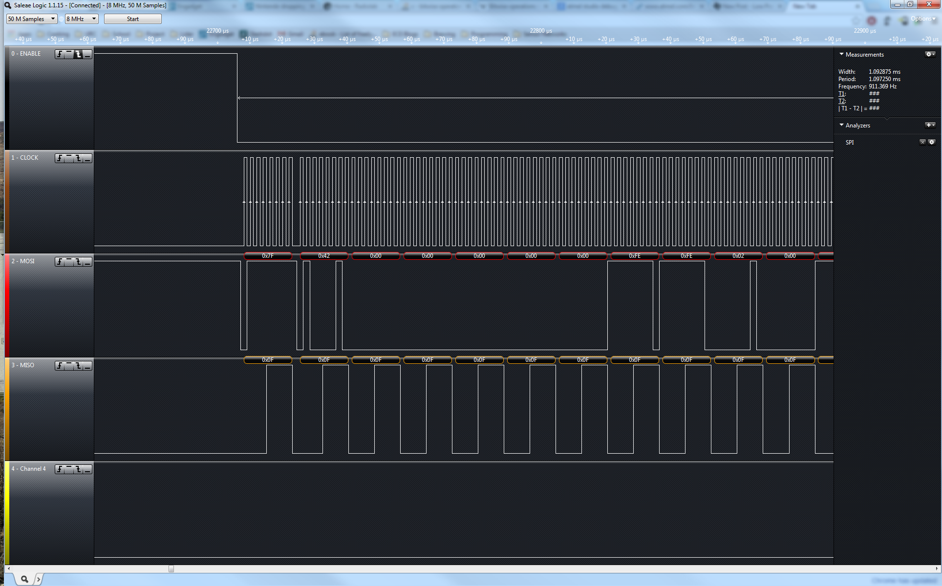
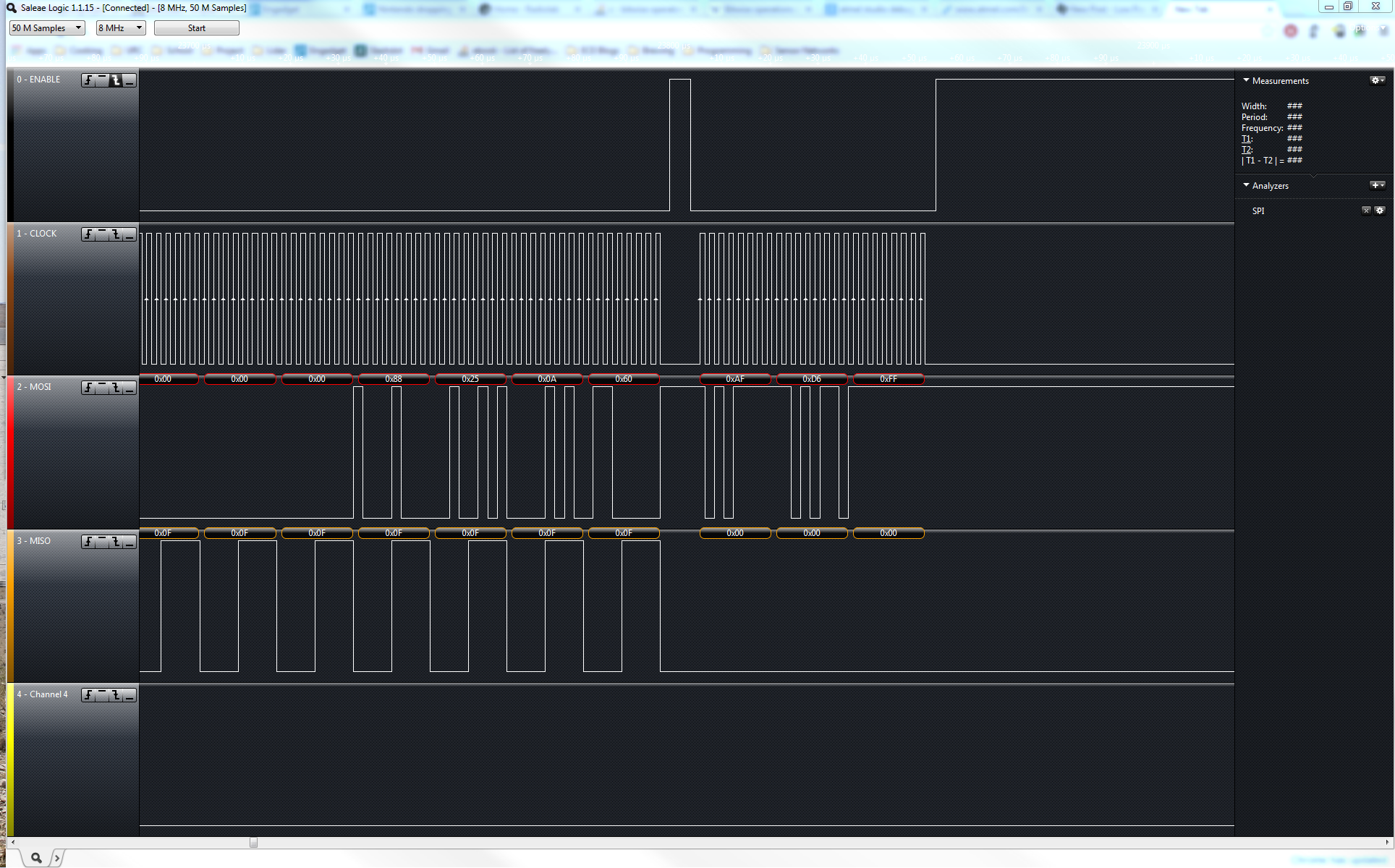
I'm currently bringing up the CC1200 EVM and I'm having an issue getting the data into the FIFO to TX.  I've validated that my cofiguration is being written as shown below and that I'm writing data to the correct address for the FIFO.  However, when I read the NUM_TX_BYTES register, I'm getting a response of 0.  I've attached two screen shots below of data I'm writing to the chip fifo, the first is the start of the fifo write, and the second is the tail end and the NUM_TX_BYTES query.  Any thoughts on what's going on?

Registers being written:

{CC_IOCFG2,             0x06},     //GPIO2 IO Pin Configuration
{CC_IOCFG0,             0x00},     //GPIO0 IO Pin Configuration
{CC_DEVIATION_M,        0xD1},     //Frequency Deviation Configuration
{CC_MODCFG_DEV_E,       0x00},     //Modulation Format and Frequency Deviation Configur..
{CC_DCFILT_CFG,         0x5D},     //Digital DC Removal Configuration
{CC_PREAMBLE_CFG0,      0x8A},     //Preamble Detection Configuration Reg. 0
{CC_IQIC,               0xCB},     //Digital Image Channel Compensation Configuration
{CC_CHAN_BW,            0xA6},     //Channel Filter Configuration
{CC_MDMCFG1,            0x40},     //General Modem Parameter Configuration Reg. 1
{CC_MDMCFG0,            0x01},     //General Modem Parameter Configuration Reg. 0
{CC_SYMBOL_RATE2,       0x3F},     //Symbol Rate Configuration Exponent and Mantissa [1..
{CC_SYMBOL_RATE1,       0x75},     //Symbol Rate Configuration Mantissa [15:8]
{CC_SYMBOL_RATE0,       0x10},     //Symbol Rate Configuration Mantissa [7:0]
{CC_AGC_REF,            0x20},     //AGC Reference Level Configuration
{CC_AGC_CS_THR,         0xEC},     //Carrier Sense Threshold Configuration
{CC_AGC_CFG1,           0x51},     //Automatic Gain Control Configuration Reg. 1
{CC_AGC_CFG0,           0x87},     //Automatic Gain Control Configuration Reg. 0
{CC_FIFO_CFG,           0x7C},     //FIFO Configuration
{CC_FS_CFG,             0x12},     //Frequency Synthesizer Configuration
{CC_PKT_CFG2,           0x00},     //Packet Configuration Reg. 2
{CC_PKT_CFG1,           0x00},     //Packet Configuration Reg. 1
{CC_PKT_CFG0,           0x20},     //Packet Configuration Reg. 0
{CC_PA_CFG1,            0x3F},     //Power Amplifier Configuration Reg. 1
{CC_PKT_LEN,            0xFF},     //Packet Length Configuration
{CC_IF_MIX_CFG,         0x1C},     //IF Mix Configuration
{CC_FREQOFF_CFG,        0x22},     //Frequency Offset Correction Configuration
{CC_MDMCFG2,            0x0C},     //General Modem Parameter Configuration Reg. 2
{CC_FREQ2,              0x5B},     //Frequency Configuration [23:16]
{CC_FREQ1,              0x80},     //Frequency Configuration [15:8]
{CC_IF_ADC1,            0xEE},     //Analog to Digital Converter Configuration Reg. 1
{CC_IF_ADC0,            0x10},     //Analog to Digital Converter Configuration Reg. 0
{CC_FS_DIG1,            0x07},     //Frequency Synthesizer Digital Reg. 1
{CC_FS_DIG0,            0xAF},     //Frequency Synthesizer Digital Reg. 0
{CC_FS_CAL1,            0x40},     //Frequency Synthesizer Calibration Reg. 1
{CC_FS_CAL0,            0x0E},     //Frequency Synthesizer Calibration Reg. 0
{CC_FS_DIVTWO,          0x03},     //Frequency Synthesizer Divide by 2
{CC_FS_DSM0,            0x33},     //FS Digital Synthesizer Module Configuration Reg. 0
{CC_FS_DVC0,            0x17},     //Frequency Synthesizer Divider Chain Configuration ..
{CC_FS_PFD,             0x00},     //Frequency Synthesizer Phase Frequency Detector Con..
{CC_FS_PRE,             0x6E},     //Frequency Synthesizer Prescaler Configuration
{CC_FS_REG_DIV_CML,     0x1C},     //Frequency Synthesizer Divider Regulator Configurat..
{CC_FS_SPARE,           0xAC},     //Frequency Synthesizer Spare
{CC_FS_VCO0,            0xB5},     //FS Voltage Controlled Oscillator Configuration Reg..
{CC_XOSC5,              0x0E},     //Crystal Oscillator Configuration Reg. 5
{CC_XOSC1,              0x03},     //Crystal Oscillator Configuration Reg. 1
  • Matthias, 

    The first thing is to make sure that you can write and read to simple registers, like CC_IOCFG2, in your code write something to it that is not the same as the RESET value. Then read it back and confirm it work. If that does not work, then you need to make sure you have pulled the RESET line of the CC1200 high and that you are waiting until after the CC1200 tells you it is "ready". 

    If this works, please post your code snippets that performs the FIFO writes.

    Regards,
    /TA 

  • Thanks for your reply.  I'm currently able to validate the registers are being correctly written for the configuration and use a routine to check for MISO low before writing.  Here's the relevant code.  If there are any holes I need to fill in I'd be glad too.

    bool cc_sendPacket(const uint8_t *txBuffer, uint16_t length, bool paEnable)
    {
    	
    	uint8_t state;
    	// Get exclusive access to the transceiver.
    	xSemaphoreTake(radioMutex, portMAX_DELAY);
    	
    	cc_disableInterrupts();
    	
    	// Cancel any current operation.
    	cc_idle();
    
    	// Set the radio mode.
    	radioMode = TX;
    	
    	if (length <= FIFO_SIZE)
    	{
    		sprintf(str, "Filled buffer with: %d bytes\r\n", length);
    		usb_puts(str);
    		
    		// Write the complete packet to the transmit FIFO.
    		cc_burstWriteRegisters(CC_FIFO, txBuffer, length);
    		txData.writeRemainingData = true;
    		txData.bytesLeft = 0;
    		txData.pBufferIndex = txBuffer+length;
    		txData.iterations = 0;
    	}
    	else if (length < MAX_VARIABLE_LENGTH)
    	{
    		txData.mode = FIXED;
    
    		//Fill the transmit FIFO with the first part of the packet.
    		cc_burstWriteRegisters(CC_FIFO, txBuffer, AVAILABLE_BYTES_IN_TX_FIFO);
    
    		txData.bytesLeft = length - AVAILABLE_BYTES_IN_TX_FIFO;
    		txData.pBufferIndex = txBuffer + AVAILABLE_BYTES_IN_TX_FIFO;
    		txData.iterations = txData.bytesLeft / AVAILABLE_BYTES_IN_TX_FIFO;
    	}
    	
    	state = cc_readExtendedRegister(CC_NUM_TXBYTES);
    	sprintf(str, "TX Bytes: 0x%02X\r\n", state);
    	usb_puts(str);
    	
    	if (txData.iterations == 0)
    	{
    		txData.writeRemainingData = true;
    	}
    	
    	cc_writeRegister(CC_IOCFG2, CC_GPIO_TXFIFO);
    	// Enable level-triggered interrupt.
    	eic_config_gpio0.eic_mode   = EIC_MODE_EDGE_TRIGGERED;
    	// Interrupt will trigger on high-level.
    	eic_config_gpio0.eic_edge   = EIC_EDGE_RISING_EDGE;
    	Disable_global_interrupt();
    	eic_line_set_config(EIC, CC_GPIO0_LINE, &eic_config_gpio0);
    	eic_line_enable(EIC, CC_GPIO0_LINE);
    	eic_line_enable_interrupt(EIC, CC_GPIO0_LINE);
    	Enable_global_interrupt();
    	
    	txData.cause = SYNC;
    	
    	// Enable the PA
    	cc_paEnable(false);
    	
    	// Start the transmission.
    	cc_strobe(CC_STX);
    
    	state = cc_readExtendedRegister(CC_MARCSTATE)&0x1F;
    	while((state != 0x14)&&(state != 0x01))
    	{
    		sprintf(str, "0x%02X\r\n", state);
    		usb_puts(str);
    		//cpu_delay_ms(10, sysclk_get_cpu_hz());
    		state = cc_readExtendedRegister(CC_MARCSTATE)&0x1F;
    	}
    	state = cc_readExtendedRegister(CC_MARCSTATE)&0x1F;
    	sprintf(str, "0x%02X\r\n", state);
    	usb_puts(str);
    	
    	// Wait for packet to be sent.
    	xSemaphoreTake(packetTransmittedSemaphore, TASK_DELAY_MS(TRANSMIT_TIMEOUT));
    	
    	state = cc_readExtendedRegister(CC_MARCSTATE)&0x1F;
    	sprintf(str, "0x%02X\r\n", state);
    	usb_puts(str);
    	
    	cc_paEnable(false);
    
    	// Give up access to the transceiver.
    	xSemaphoreGive(radioMutex);
    	
    	return true;
    }
    
    uint8_t cc_burstWriteRegisters(uint8_t address, uint8_t* val, uint8_t len)
    {
    	
    	uint8_t header[2];
    	uint8_t length;
    	uint8_t status;
    	
    	if((address & 0xFF00))
    	{
    		header[0] = CC_EXTENDED_REG_ADDR | CC_WRITE | CC_BURST;
    		header[1] = (address & 0xFF);
    		length = 2;
    	}
    	else
    	{
    		header[0] = address | CC_WRITE | CC_BURST;;
    		length = 1;
    	}
    
    	spi_select_device(CC_SPI, &ccSpiDevice);
    	
    	cc_checkReady();
    
    	//Write the header
    	spi_write_packet(CC_SPI, &header, length);
    	
    	// Get the status byte.
    	while (!spi_is_rx_ready(CC_SPI));
    	spi_read_single(CC_SPI, &status);
    
    	// Write the register values.
    	spi_write_packet(CC_SPI, val, len);
    	
    	// Get the status byte.
    	while (!spi_is_rx_ready(CC_SPI));
    	spi_read_single(CC_SPI, &status);
    
    	spi_deselect_device(CC_SPI, &ccSpiDevice);
    
    	return status;
    }
    
    //Definitions used:
    
    //Standard FIFO Access
    #define CC_FIFO				0x3F
    
    //Commands
    #define CC_BURST			0x40
    #define CC_READ				0x80
    #define CC_WRITE			0x00
    
    #define FIFO_SIZE			128
    #define CC_NUM_TXBYTES      0x2FD6
    
    void cc_checkReady(void)
    {
    	spi_disable(SPI);
    	// The data sheet indicates that we must wait until the SO pin goes low
    	// before transferring the header byte.
    	ioport_reset_pin_mode(CC_SPI_CS_PIN);
    	ioport_enable_pin(CC_SPI_CS_PIN);
    	ioport_set_pin_dir(CC_SPI_CS_PIN, IOPORT_DIR_OUTPUT);
    	ioport_set_pin_level(CC_SPI_CS_PIN, LOW);
    	ioport_reset_pin_mode(CC_SPI_MISO_PIN);
    	ioport_enable_pin(CC_SPI_MISO_PIN);
    	ioport_set_pin_dir(CC_SPI_MISO_PIN, IOPORT_DIR_INPUT);
    	while(ioport_get_pin_level(CC_SPI_MISO_PIN));
    	ioport_set_pin_mode(CC_SPI_CS_PIN, CC_SPI_CS_MODE);
    	ioport_disable_pin(CC_SPI_CS_PIN);
    	ioport_set_pin_mode(CC_SPI_MISO_PIN, CC_SPI_MISO_MODE);
    	ioport_disable_pin(CC_SPI_MISO_PIN);
    	spi_enable(SPI);	
    }

     
  • Matthias, 

    As far as I can see your "checkReady" routine breaks the communication. The only thing you need to do is to make sure the SO pins goes low. Like, so

    while(ioport_get_pin_level(CC_SPI_MISO_PIN));

    But in your code you are deselecting the chip right after you check for the SO pin to be low, therefore any communication following that does not get recognized.

    I recommend making you checkReady a lot simpler:

    void cc_checkReady(void)
    {
     ioport_reset_pin_mode(CC_SPI_MISO_PIN);
     	ioport_enable_pin(CC_SPI_MISO_PIN);
     	ioport_set_pin_dir(CC_SPI_MISO_PIN, IOPORT_DIR_INPUT);
      	while(ioport_get_pin_level(CC_SPI_MISO_PIN));
     	ioport_set_pin_mode(CC_SPI_MISO_PIN, CC_SPI_MISO_MODE);
     	ioport_disable_pin(CC_SPI_MISO_PIN);
    

    }

    You have already selected the chip before you called the subroutine. Don't mess with the chip select pin more that absolutely needed.

    Regards,
    /TA 

  • Oddly enough... the way Atmel writes their SPI library, "selecting" the line doesn't actually appear to drive the line low.  It maintains state until you actually cause an access and the ioport_get_pin_value function returns the last state of the pin it had as an IO pin... I don't think it actually updates the value when a peripheral mux is enabled.  This was the best implementation I could come up with for the Atmel ASF libraries. If you look at the logic captures, it appears that the CS line actually stays low if you leave it in that state until the peripheral takes over at the start of the SPI write (which would drive it low).  This whole thing was pretty maddening at first.

    As far as my original issue was concerned, I tore down my boards, plugged back into the TXRX TI board, did another run with my settings minus the IO config, and things worked.  So I put everything back together with my SAM4L in the loop and things seem to be working now.. I may have failed to do a hard reset on the CC1200 after I wrote some bad configs in my initial bring up that were being held.  Seems to be working fine as a replacement for the old CC1101 we were using.  

    As an aside... are there any curves available for the expected gains for the CC1200 DSSS implementation?  Given the effect a very similar scheme seems to have on the link budget for the SX1272/3/6 by Semtech, I'm hoping to be able to pick up a good chunk link by enabling the mode.