This thread has been locked.

If you have a related question, please click the "Ask a related question" button in the top right corner. The newly created question will be automatically linked to this question.

CC1020 RX Problem

Other Parts Discussed in Thread: CC1020

Hello

I am configuring CC1020 as RX and following are the default settings

// X-tal frequency: 14.745600 MHz    Internal
// X-tal accuracy: +/-  5 ppm
// RF frequency A: 927.678900 MHz    Active      Rx
// RF frequency B: 927.678900 MHz    Inactive    Tx
// Frequency separation: 216 kHz
// Data rate: 38.400 kBaud
// Data Format: Manchester        Accurate
// RF output power: +5 dBm
// Channel width: 500 kHz
// Modulation: FSK        Dithering enabled
// Lock: Continuous
// Carrier sense offset:   0 dBm    DCLK squelch disabled
// Operator Mode: Tx

Later on I am configuring the RX frequency to 902.9751 MHz.

My transmitter has the following spectrum

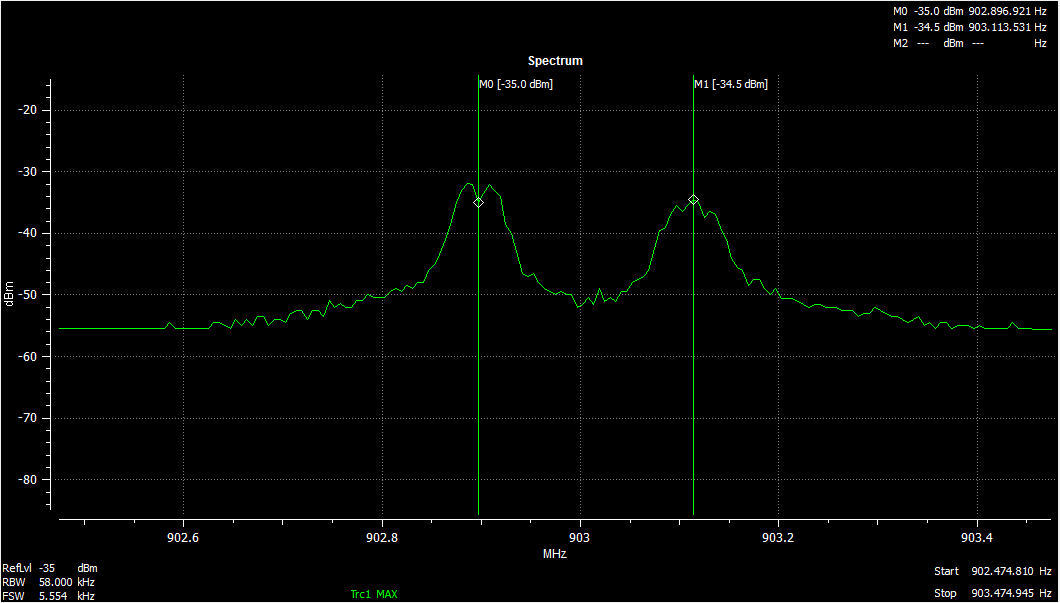
But when I configure CC1020 as transmitter the spectrum look a little different as below.

when I use CC1020 on the extra board I have as transmitter, then the RX using CC1020 work. But with the original transmitter, RX does not work. I can see that only random patterns are coming from the DIO pin when trying to receive with the original transmitter.

Although I set 216kHz for deviation, CC1020 produce around 256kHz of deviation is this fine?

How much is the allowable difference in centre frequency between TX and RX ?

  • Note that CC1020 uses Separation which is 2xdeviation. Try to use the same deviation on Rx and Tx side.

  • Hi TER

    Thank you for looking into my question.

    I have set the separation to be 216kHz and when I measure using spectrum analyzer as shown in my first post above, I am getting256kHz.

  • Could you post your register settings?

  • Following are the register settings

    const char DefaultConfig915[32] =
    {
    0x0F, // 0x01, INTERFACE
    0xFF, // 0x02, RESET
    0x8F, // 0x03, SEQUENCING
    0x3E, // 0x04, FREQ_2A
    0x24, // 0x05, FREQ_1A
    0x35, // 0x06, FREQ_0A
    0x27, // 0x07, CLOCK_A
    0x3E, // 0x08, FREQ_2B
    0x29, // 0x09, FREQ_1B
    0x89, // 0x0A, FREQ_0B
    0x27, // 0x0B, CLOCK_B
    0x44, // 0x0C, VCO
    0x51, // 0x0D, MODEM
    0x5F, // 0x0E, DEVIATION
    0xEF, // 0x0F, AFC_CONTROL
    0x00, // 0x10, FILTER
    0x61, // 0x11, VGA1
    0x55, // 0x12, VGA2
    0x34, // 0x13, VGA3
    0x3E, // 0x14, VGA4
    0x20, // 0x15, LOCK
    0x76, // 0x16, FRONTEND
    0x87, // 0x17, ANALOG, RX=87/TX=87
    0x10, // 0x18, BUFF_SWING
    0x25, // 0x19, BUFF_CURRENT
    0xAE, // 0x1A, PLL_BW
    0x34, // 0x1B, CALIBRATE
    0xB0, // 0x1C, PA_POWER
    0xF0, // 0x1D, MATCH
    0x00, // 0x1E, PHASE_COMP
    0x00, // 0x1F, GAIN_COMP
    0x00  // 0x20, POWERDOWN
    };

  • You write: "But with the original transmitter, RX does not work."

    Is the loop filter set correctly to allow for 38.4 kbps data rate?


    To measure the frequency deviation (or separation = 2 x deviation) use the frequency vs time option in the spectrum analyzer. Measuring the deviation in the frequency domain is not all that accurate 

  • I have used the resistor and capacitor  values suggested by TI's SmartRF studio for loop filter.

    I have TI's USB spectrum analyzer. It does not have Frequency vs Time option.

  • I've never used this spectrum, have you tested the accuracy with a signal generator? I suspect that this is more a indicator than a analyzer.

  • Hi TER

    I only have a limited test setup and this USB analyzer is one of them. Yes, this is more of an indicator


    I am trying to interface CC1020 to ADF7025. For trouble shooting I configured both as TX and RX to verify firmware and hardware. Following combinations work without any problem

    CC1020 as TX - 7025 as receive - Working fine

    CC1020 as TX - another CC1020 as receive - Working fine

    7025 as TX - another 7025 as receive - Working fine

    7025 as TX - CC1020 as receive - This is having problem

    I could not figure out what is wrong.

  • If you read out the RSSI value when 7025 is tx an 1020 is receive do you see increased value when you tx? Just want to make sure you are on the correct frequency.
  • how to configure cc1020 as transmitter?and what spectrum i should get?
  • how to configure cc1020 with pc as transmitter?
  • HOW TO CONFIGURE CC1020 AS TRANSMITTER
  • Dash: Have you tried SmartRF Studio?
  • yeah i have tried.
    I connected CC1020EB to pc through parallel port cable and using channel A with RF frequency of 869.31Mhz. But in spectrum analyzer i'm getting frequency as 320Mhz. so please tell me the clear procedure to configure CC1020 as transmitter.

    thanks in advance..and thanks a lot Mr. TER for your VALUABLE reply
  • - Please confirm that you press "reset", "update" "calibrate" in that order.
    - If you do, please take a screen shot of your SmartRF Studio window showing which settings you are using.

    A CC1020EB will send a tone on the correct frequency out of the box if the sequence above is followed.
  • procedure to configure cc1020 as transmitter: 

    I am using these settings. please have a look

    // X-tal frequency: 14.745600 MHz    Internal
    // X-tal accuracy: +/-  5 ppm
    // RF frequency B: 927.678900 MHz   active    Tx
    // Frequency separation: 216 kHz
    // Data rate: 38.400 kBaud
    // Data Format: Manchester        Accurate
    // RF output power: +5 dBm
    // Channel width: 500 kHz
    // Modulation: FSK      
    // Lock: Continuous
    // Carrier sense offset:   0 dBm    DCLK squelch disabled
    // Operator Mode: Tx

    after this i followed reset-configure-calibrate

    and then selected register option. The resistor values are,

    from main TO powerdown values are =0x01, 0F, FF, 8F, 3E, 24, 35, 27, 3E, 29, 89, 27, 44, 51, 5F, EF, 00, 61, 55, 34, 3E, 20, 76, 87, 10, 25, AE, 34, B0, F0, 00, 00, 00

    after this again i followed reset-configure-calibrate.


    *I connected an evaluation board to regulated power supply with fixed 5v/2A.  AM I RIGHT??

  • What is the use of diagnose? I am getting  this error message      "parallel port is not initiated. Diagnose is not possible"    after selecting diagnose option.

  • SmartRF Studio that supports CC1020 only works on Windows XP (and older). What are you using?