Hi,
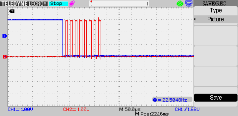
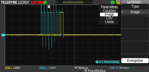
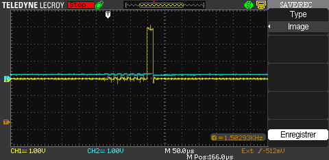
I have problems to communicate with CC1200 emk using SPI. Indeed, to communicate with I use a STM32F4-discovery board and only i have in output is 0xFF while I have 0 at the scope (0.3V to be accurate). Moreover at the scope I can clearly see the STM32's clock and MOSI pin with good sync and 3V for 1 and 0V for 0. I supply CC1200 emk with 3.3V.
After reading the CC1200's datasheet, I configured my STM32's SPI like this :
- SPI full duplex - CPHA and CPOL = 0
- 8bits data transfer - I use 256 of clk prescaler to be sure to be under 10MHz
- MSB 1st - Master mode
I think the problem is that the CC1200 doesn't understand what I'm sending with my controller but i really don't know why. I checked some points :
- changed the CPHA
- disable pull-down resistor
- verify CC1200 works : The GPIO 0 is by default on Ext_Osc_En and with an extern interruption I can detect a rising edge when I power off and power on the CC1200. If you have better ideas to know if CC1200 works correctly I would like to hear them.
I can't use devKit for sub 1Ghz module kit because it's simply too expansive and I think to use SPI with CC1200 this device will not help me.
I'm beginner with SPI and CC1200 and I want to understand what are my mistakes. Thank you for your help, here is my code for the STM32F4 :
/******************** (C) COPYRIGHT 2009 Embest Info&Tech Co.,LTD. ************
* File Name : main.c
* Author :
* Date First Issued : 28/03/2013
* Description : Main program body
*******************************************************************************
*******************************************************************************
* History:
* 28/03/2013 : V1 initial version
* 13/06/2013 : V2
*******************************************************************************/
/* Includes ------------------------------------------------------------------*/
#include "stm32f4xx.h"
#include <stdio.h>
#include <string.h>
#include <stdlib.h>
#include <stdbool.h>
#include "delay.h"
#include "utils.h"
/* Private typedef -----------------------------------------------------------*/
/* Private define ------------------------------------------------------------*/
#define DBGU_RX_BUFFER_SIZE 256
#define TEST_BUFFERSIZE 128
/* Private macro -------------------------------------------------------------*/
/* Private variables ---------------------------------------------------------*/
uint8_t DBGU_RxBuffer[DBGU_RX_BUFFER_SIZE];
uint32_t DBGU_RxBufferTail = 0;
uint32_t DBGU_RxBufferHead = 0;
bool DBGU_InputReady = false;
bool quit_flag = false;
/* Private function prototypes -----------------------------------------------*/
#ifdef __GNUC__
/* With GCC/RAISONANCE, small printf (option LD Linker->Libraries->Small printf
set to 'Yes') calls __io_putchar() */
#define PUTCHAR_PROTOTYPE int __io_putchar(int ch)
#else
#define PUTCHAR_PROTOTYPE int fputc(int ch, FILE *f)
#endif /* __GNUC__ */
void DBGU_Init(void);
bool DBGU_RxBufferEmpty(void);
uint8_t DBGU_GetChar(void);
/* Private functions ---------------------------------------------------------*/
/**
* @brief Main program.
* @param None
* @retval None
*/
int main(void)
{
uint8_t val_recue_spi2 = 0x00;
HwInit();
SysTick_Configuration();
init_SPI2();
DBGU_Init();
printf("\n\rHello, Embedded World!\n\r");
GPIO_WriteBit(GPIOC, GPIO_Pin_11, Bit_SET); // set PC11 (nCS) High
/* Infinite loop */
while (1) {
printf("\n\r Valeur de nCS %d ",GPIO_ReadInputDataBit(GPIOC, GPIO_Pin_11));
printf("\n\r Lecture de la broche MISO : %d ",GPIO_ReadInputDataBit(GPIOB, GPIO_Pin_14));
printf("\n\r *** Verification du statut du module ***");
GPIO_WriteBit(GPIOC, GPIO_Pin_11, Bit_RESET); // set PC11 (nCS) Low
printf("\n\r Valeur de nCS %d ",GPIO_ReadInputDataBit(GPIOC, GPIO_Pin_11));
mdelay(20); //20ms
//Début de transmission
printf("\n\r Lecture de la broche MISO : %d ",GPIO_ReadInputDataBit(GPIOB, GPIO_Pin_14));
//Ecriture dans le registre IOCFG2
val_recue_spi2 = SPI2_send(0x01);
mdelay(2);
printf("\n\r Statut module RF : %d",val_recue_spi2);
val_recue_spi2 = val_recue_spi2 >> 4;
printf("\n\r Apres le shift : %d",val_recue_spi2);
//Ecrire 5 dans le registre IOCFG2
//Assigne la broche GPIO 2 à TXFIFO_UNDERFLOW (juste pour tester l'écriture)
val_recue_spi2 = SPI2_send(0x05);
mdelay(2);
printf("\n\r Lecture de la broche MISO : %d ",GPIO_ReadInputDataBit(GPIOB, GPIO_Pin_14));
//Lecture du registre IOCFG2
SPI2_send(0x81);
mdelay(1);
//Envoi d'un dummy byte avec commande SNOP pour recevoir la donnée modifiée
val_recue_spi2 = SPI2_send(COMMANDE_SNOP);
printf("\n\r valeur Registre IOCFG2 : %d",val_recue_spi2);
//Fin transmission
GPIO_WriteBit(GPIOC, GPIO_Pin_11, Bit_SET); // set PC11 (nCS) High
printf("\n\r Valeur de nCS %d ",GPIO_ReadInputDataBit(GPIOC, GPIO_Pin_11));
mdelay(2000);
}
printf("\n\rGoodbye, Embedded World!\n\r");
}
/**
*****************************************************************************
** File : utils.c
**
** Abstract : outils de gestion des périphériques
** Author : Erwan Moréac
**
** Date : 16-01-2013
*****************************************************************************
*/
/* Includes ------------------------------------------------------------------*/
#include "stm32f4xx.h"
#include "stm32f4xx_spi.h"
#include "utils.h"
#include <stdarg.h>
#include <ctype.h>
/**************************************************************************
* @descr Initialise les differents péripheriques
* @param None
* @retval None
*************************************************************************/
void HwInit( void )
{
CLKInit(); // Initialise la clock
NVIC_Config(); // Initialise Interruptions
EXT_IntInit_Encodeur_1(); //Initialise l'interruption externes line1
}
/*------------------------------------------------------------------------
* Peripheral Use External Clock at 8 MHz
* -----------------------------------------------------------------------
* PLL_M 8
* PLL_N 336
* PLL_Q 7
* PLL_P 2
* SYSCLK 32 MHz
* -----------------------------------------------------------------------*/
void CLKInit( void)
{
SystemInit(); // Setup Microcontroller System
RCC->CR = RCC->CR | RCC_CR_HSEON; // HSE Oscillator ON
// PLLCFGR n'est pas présent sur la stm32l100
RCC->PLLCFGR = RCC->PLLCFGR |
RCC_PLLCFGR_PLLQ_0 | // PLLQ = 7 (0111)
RCC_PLLCFGR_PLLQ_1 |
RCC_PLLCFGR_PLLQ_2 |
RCC_PLLCFGR_PLLSRC_HSE | // HSE oscillator selected as PLL clock entry
RCC_PLLCFGR_PLLN_8 | // PLLN = 336 (101010000)
RCC_PLLCFGR_PLLN_6 |
RCC_PLLCFGR_PLLN_4 |
RCC_PLLCFGR_PLLM_3; // PLLM = 8 (001000)
RCC->CFGR = RCC->CFGR | RCC_CFGR_SW_PLL; // PLL selected as system clock
SystemCoreClockUpdate(); // Update SystemCoreClock variable 32 MHz
RCC_PCLK2Config(RCC_HCLK_Div8); // Prescaler de APB2 configurer à 16
}
/*------------------------------------------------------------------------
* Peripheral SPI 2
* -----------------------------------------------------------------------
* Device RF communication by CC1200
* SClk PB13
* MISO PB14
* MOSI PB15
* SS1 PC11
* Clock 32 MHz
* -----------------------------------------------------------------------*/
// this function initializes the SPI2 peripheral
void init_SPI2(void){
GPIO_InitTypeDef GPIO_InitStruct;
SPI_InitTypeDef SPI_InitStruct;
// enable clock for used IO pins
RCC_AHB1PeriphClockCmd(RCC_AHB1Periph_GPIOB, ENABLE);
//RCC_AHBPeriphClockCmd(RCC_AHBPeriph_GPIOA, ENABLE);
/* configure pins used by SPI1
* PB13 = SCK
* PB14 = MISO
* PB15 = MOSI
*/
GPIO_InitStruct.GPIO_Pin = GPIO_Pin_15 | GPIO_Pin_14 | GPIO_Pin_13;
GPIO_InitStruct.GPIO_Mode = GPIO_Mode_AF;
GPIO_InitStruct.GPIO_OType = GPIO_OType_PP;
GPIO_InitStruct.GPIO_Speed = GPIO_Speed_50MHz;
GPIO_InitStruct.GPIO_PuPd = GPIO_PuPd_NOPULL;
GPIO_Init(GPIOB, &GPIO_InitStruct);
// connect SPI2 pins to SPI alternate function
GPIO_PinAFConfig(GPIOB, GPIO_PinSource13, GPIO_AF_SPI2);
GPIO_PinAFConfig(GPIOB, GPIO_PinSource14, GPIO_AF_SPI2);
GPIO_PinAFConfig(GPIOB, GPIO_PinSource15, GPIO_AF_SPI2);
// enable clock for used IO pins
RCC_AHB1PeriphClockCmd(RCC_AHB1Periph_GPIOC, ENABLE);
//RCC_AHBPeriphClockCmd(RCC_AHBPeriph_GPIOC, ENABLE);
/* Configure the chip select pin
in this case we will use PC11 */
GPIO_InitStruct.GPIO_Pin = GPIO_Pin_11;
GPIO_InitStruct.GPIO_Mode = GPIO_Mode_OUT;
GPIO_InitStruct.GPIO_OType = GPIO_OType_PP;
GPIO_InitStruct.GPIO_Speed = GPIO_Speed_50MHz;
GPIO_InitStruct.GPIO_PuPd = GPIO_PuPd_UP;
GPIO_Init(GPIOC, &GPIO_InitStruct);
GPIOC->BSRRL |= GPIO_Pin_11; // set PC11 high
// enable peripheral clock
RCC_APB1PeriphClockCmd(RCC_APB1Periph_SPI2, ENABLE);
/* configure SPI2 in Mode 0
* CPOL = 0 --> clock is low when idle
* CPHA = 0 --> data is sampled at the first edge
*/
SPI_InitStruct.SPI_Direction = SPI_Direction_2Lines_FullDuplex; // set to full duplex mode, seperate MOSI and MISO lines
SPI_InitStruct.SPI_Mode = SPI_Mode_Master; // transmit in master mode, NSS pin has to be always high
SPI_InitStruct.SPI_DataSize = SPI_DataSize_8b; // one packet of data is 8 bits wide
SPI_InitStruct.SPI_CPOL = SPI_CPOL_Low; // clock is low when idle
SPI_InitStruct.SPI_CPHA = SPI_CPHA_1Edge; // data sampled at first edge
SPI_InitStruct.SPI_NSS = SPI_NSS_Soft | SPI_NSSInternalSoft_Set; // set the NSS management to internal and pull internal NSS high
SPI_InitStruct.SPI_BaudRatePrescaler = SPI_BaudRatePrescaler_256; // SPI frequency is APB2 frequency / 32 pour être <10MHz qui est la fmax du capteur
SPI_InitStruct.SPI_FirstBit = SPI_FirstBit_MSB;// data is transmitted MSB first
SPI_Init(SPI2, &SPI_InitStruct);
SPI_Cmd(SPI2, ENABLE); // enable SPI2
}
/*------------------------------------------------------------------------
* Peripheral EXT_IntInit_Encodeur_1
* -----------------------------------------------------------------------
* Device RF communication by CC1200
* Pin PC1
* Mode Rising edge
* Clock 32 MHz
* -----------------------------------------------------------------------*/
//Permet de détecter le passage à l'état haut de la broche GPIO 0 du module RF
void EXT_IntInit_Encodeur_1(void){
GPIO_InitTypeDef GPIO_InitStructure;
EXTI_InitTypeDef EXTI_InitStructure;
/*Active l'horloge des broches GPIOA */
RCC_AHB1PeriphClockCmd(RCC_AHB1Periph_GPIOA, ENABLE);
//RCC_AHBPeriphClockCmd(RCC_AHBPeriph_GPIOC,ENABLE);
/*Configure la broche PC1 pour l'interruption externe 1*/
RCC_APB2PeriphClockCmd(RCC_APB2Periph_SYSCFG, ENABLE);
GPIO_InitStructure.GPIO_Mode = GPIO_Mode_IN;
GPIO_InitStructure.GPIO_PuPd = GPIO_PuPd_DOWN;
GPIO_InitStructure.GPIO_Pin = GPIO_Pin_1;
GPIO_Init(GPIOC, &GPIO_InitStructure);
/*Permet le déclenchement de l'int 1 sur une broche GPIOC*/
SYSCFG_EXTILineConfig(EXTI_PortSourceGPIOC, EXTI_PinSource1);
/*Configuration de l'EXTI_1*/
EXTI_InitStructure.EXTI_Line = EXTI_Line1;
EXTI_InitStructure.EXTI_Mode = EXTI_Mode_Interrupt;
EXTI_InitStructure.EXTI_Trigger = EXTI_Trigger_Rising;
EXTI_InitStructure.EXTI_LineCmd = ENABLE;
EXTI_Init(&EXTI_InitStructure);
RCC_APB2PeriphClockCmd(RCC_APB2Periph_SYSCFG, ENABLE);
}
/*------------------------------------------------------------------------
* Function SPI2_send
* -----------------------------------------------------------------------
* @descr Send 8bits via SPI 2
* @param data
* @retval received data from SPI data register
* -----------------------------------------------------------------------*/
/* This funtion is used to transmit and receive data
* with SPI1
* data --> data to be transmitted
* returns received value
*/
uint8_t SPI2_send(uint8_t data){
/* Check the parameters */
assert_param(IS_SPI_ALL_PERIPH(SPI2));
SPI2->DR = data; // write data to be transmitted to the SPI data register
while( !(SPI2->SR & SPI_I2S_FLAG_TXE) ); // wait until transmit complete
while( !(SPI2->SR & SPI_I2S_FLAG_RXNE) ); // wait until receive complete
while( SPI2->SR & SPI_I2S_FLAG_BSY ); // wait until SPI is not busy anymore
return SPI2->DR; // return received data from SPI data register
}
/*------------------------------------------------------------------------
* Peripheral NVIC - Nested Vectored Interrupt Controller
* -----------------------------------------------------------------------
* function Enable Interrupt and Configure the Priority
* -----------------------------------------------------------------------*/
void NVIC_Config(void)
{
NVIC_InitTypeDef NVIC_InitStructure;
/* Selectionne la priorite du group */
NVIC_PriorityGroupConfig(NVIC_PriorityGroup_4);
/* Enable the EXT_Int 2 interrupt - GPIO 2 of CC1200*/
NVIC_InitStructure.NVIC_IRQChannel = EXTI2_IRQn;
NVIC_InitStructure.NVIC_IRQChannelPreemptionPriority = 0x02;
NVIC_InitStructure.NVIC_IRQChannelSubPriority = 0x01;
NVIC_InitStructure.NVIC_IRQChannelCmd = ENABLE;
NVIC_Init(&NVIC_InitStructure);
/* Enable the EXT_Int 1 interrupt - GPIO 0 of CC1200*/
NVIC_InitStructure.NVIC_IRQChannel = EXTI1_IRQn;
NVIC_InitStructure.NVIC_IRQChannelPreemptionPriority = 0x02;
NVIC_InitStructure.NVIC_IRQChannelSubPriority = 0x02;
NVIC_InitStructure.NVIC_IRQChannelCmd = ENABLE;
NVIC_Init(&NVIC_InitStructure);
}
/**
*****************************************************************************
** File : delay.c
** Abstract :
** Environment :
** Author : Erwan Moréac
** Date : 16-01-2013
**
*****************************************************************************
*/
#include "stm32f4xx.h"
static uint32_t TimingDelay;
extern uint32_t SystemCoreClock;
void SysTick_Configuration(void)
{
if(SysTick_Config(SystemCoreClock / 1000)) {
while(1);
}
}
void mdelay(u32 ms)
{
TimingDelay = ms;
while(TimingDelay != 0);
}
void TimingDelay_Decrement(void)
{
if (TimingDelay != 0x00) {
TimingDelay--;
}
}
/**
******************************************************************************
* @file stm32l1xx_it.c
* @author MCD Application Team
* @version V1.0.0
* @date 29-July-2013
* @brief Main Interrupt Service Routines.
* This file provides template for all exceptions handler and
* peripherals interrupt service routine.
******************************************************************************
* @attention
*
* <h2><center>© COPYRIGHT 2013 STMicroelectronics</center></h2>
*
* Licensed under MCD-ST Liberty SW License Agreement V2, (the "License");
* You may not use this file except in compliance with the License.
* You may obtain a copy of the License at:
*
* http://www.st.com/software_license_agreement_liberty_v2
*
* Unless required by applicable law or agreed to in writing, software
* distributed under the License is distributed on an "AS IS" BASIS,
* WITHOUT WARRANTIES OR CONDITIONS OF ANY KIND, either express or implied.
* See the License for the specific language governing permissions and
* limitations under the License.
*
******************************************************************************
*/
/* Includes ------------------------------------------------------------------*/
#include "stm32f4xx_it.h"
#include "main.h"
#include <stdio.h>
/*------------------------------------------------------------------------
* INT.GLO Interruption externe 1
* -----------------------------------------------------------------------
* Int. EXTI1_IRQHandler
* Quand Chaque fronts montants de PC1 (clk externe prêt pour communication)
* Appareil Module RF CC1200
* -----------------------------------------------------------------------*/
void EXTI1_IRQHandler(void){
printf("\n\rInterruption Externe : ");
printf("\n\r Signal PC1 : %d!",GPIO_ReadInputDataBit(GPIOC, GPIO_Pin_1));
if(EXTI_GetITStatus(EXTI_Line1) == SET)
{
/* Clear EXTI_Line1 interrupt pending bit */
EXTI_ClearITPendingBit(EXTI_Line1);
//STM_EVAL_LEDOff(LED4);
printf("\n\r CC1200 ready!");
//Delay(500000);
}
}
/**
* @brief This function handles SysTick Handler.
* @param None
* @retval None
*/
void SysTick_Handler(void)
{
TimingDelay_Decrement();
}