This thread has been locked.

If you have a related question, please click the "Ask a related question" button in the top right corner. The newly created question will be automatically linked to this question.

Problem with CC1125EM 420/470MHz Reference Design

Other Parts Discussed in Thread: CC1125

Hi:

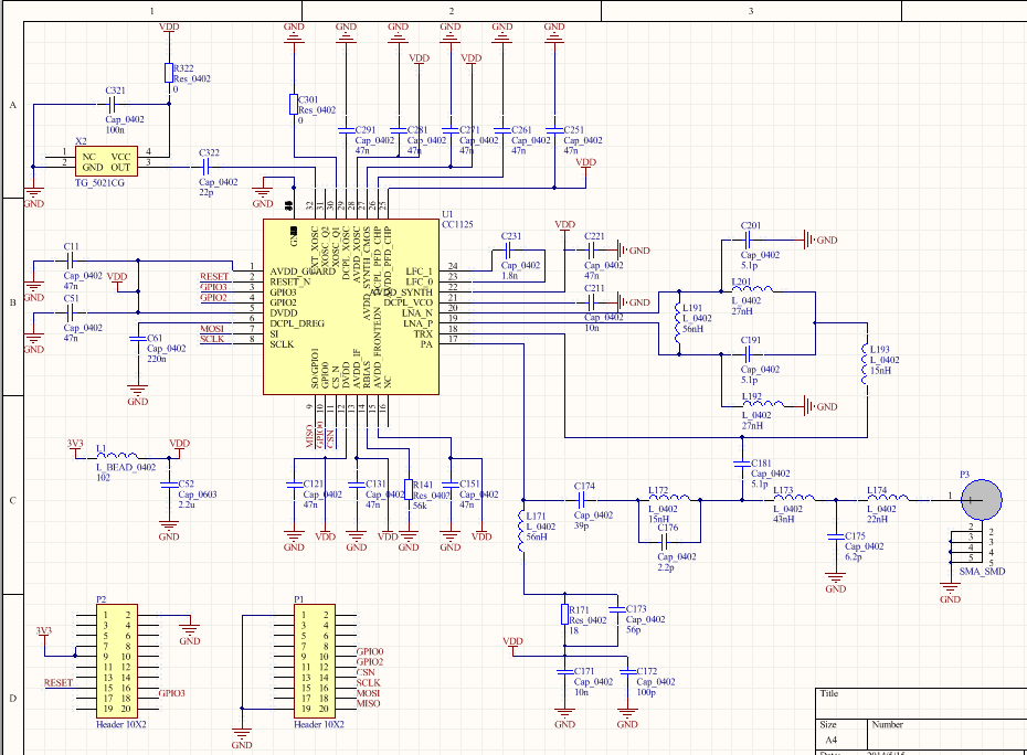
I design a board with CC1125EM 420/470MHz Reference Design(http://www.ti.com/tool/cc1125em-420-470-rd). But unfortunately, I failed. 

The observations with my testing are shown as below:

1.It works with SmartRF Studio only when I run TX. I have observed with the spectrum and got the right wave. But if I run RX, it doesn't work. And if I try more, I will get the messege below.

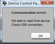
The  parameters I used are from  settings.

2.I tried to run the Easylink code (http://www.ti.com/lit/zip/swrc253) with the parameters exported from SmartRF Studio, but it doesn't work. It stopped in the manualCalibration.

I nearly copy the TI CC1125EM 420/470MHz Reference Design totally. I use TCXO which is TG_5021CG(40MHz).

I don't know why it doesn't work. Should I adjust some components from the Reference Design?

Thanks!

  • It sounds like you have a slightly poor connection between your board and the MCU. Monitor the SPI interface and the reset line to see if the communication is as expected.
  • Hi TER,

    Thanks for your quick reply.

    I think my SPI communication has no problem. Because I test register write & read, it works.

    For example, I run the code below:

    writeByte = 0x12;
    cc112xSpiWriteReg(0x01, &writeByte, 1);
    cc112xSpiReadReg(0x01, &writeByte, 1);

    I write a byte to a register and read it immediately. It's correct. I test with several registers, include extended registers(eg. 0x2F01). So can I believe SPI is OK?

    And I also test the reset line to confirm it's OK too.

    suspect that my TCXO on CC1125 board doesn't work properly. Do you have any methods to test it?

    Thanks very much.

  • Where in the Manual Calibration does the code stop? Please take a snapshot.

    Why do you suspect the TCXO? If you are able to program the chip the clock seems to be functional.

    What do you use to control the ref design? Is it possible to post a picture of your setup?

  • The code lost in the loop below:

    trxSpiCmdStrobe(CC112X_SCAL);
    do {
    cc112xSpiReadReg(CC112X_MARCSTATE, &marcstate, 1);
    } while (marcstate != 0x41);

    It means that CC1125 can't return from CAL status to IDEL status. So I think TCXO has some problem which result in that CC1125 can't complete the Manual Calibration.

    I copy the ref design schematic totally, and design a 4-layer layout. Even my  components and wires positions are as same as the ref design.

  • A TCXO is a component giving a clock to the CC1125, it is no feedback from the chip to it. Did you mean something else?

    Read out the MARCSTATE before strobing SCAL and also report which MARCSTATE it reads out when stuck in the loop.

    Which MCU are you using and how have you connected the MCU to your board?

  • I use my board on TrxEB, which I board from TI. I use TI CC1125EM 869 MHz board on it, and it's perfect.

    Before strobing SCAL, MARCSTATE =0x41, IDLE status, no problem.

    After strobing SCAL, MARCSTATE =0x04. I have checked the user guide. But I don't know what it mean.

  • From my understanding it is not possible to be stuck in MARCSTATE=0x04, this is a state that just contain a small delay. If you skip manual calibration (just strobe SCAL)  does you code work then?

    Please post your schematic.

  • If I skip manual calibration, only strobe SCAL, there are still errors. Because the chip status can't return to IDLE status. So TX can't run. If I strobe IDLE or don't strobe SCAL, TX can run, but there are no singal from the radio. (observed with the spectrum).

    Is there any possible that the CC1125 chip has something wrong? Especially frequency synthesizer part.

    I just have done my 5st board, it woks, which surprise me. But my last 4 boards have the same problem.

    There is my schematic:

  • Hm,

    - How do you assemble the boards? Do you solder the boards yourself?

    - On the failing boards, what is the voltage on the DCPL pins? RBIAS? It could be that you have managed to partially destroy the chip.

    The schematic looks good.

  • I have checked the pins' voltage, DCPL pins are really abnormal.

    Yes, I solder the boards by myself. Maybe I have destroyed the chips.

    Well, thank you very much for helping me a lot.

  • When soldering of chips you should use a hot plate like this one: http://www.directindustry.com/prod/unitemp-gmbh/digital-laboratory-hot-plates-61496-697685.html to have reasonably control of the soldering process.

  • Hi, TER.

    I do something more, so I have more questions.

    assemble 2 more boards at the temperature of 250 ℃. I think at this  temperature chips won't be destroyed.

    But they still have the same problems.

    I find that if I strobe SCAL or SRX, the chip will sink into a state of chaos. The VCC will down to 2.5V(should be 3.3V), and crystal will be not stable. I observed these in the oscilloscope.

    But if I strobe STX, there won't be any problems. So I can transmit singals successfully with auto-calibration . 

    I doubt if I bought some damaged CC1125 chips.

    I live in China so I don't have many methods to buy TI chips. Could you please give me any suggestions in purchase?

    Thank you very much!