This thread has been locked.

If you have a related question, please click the "Ask a related question" button in the top right corner. The newly created question will be automatically linked to this question.

CC120x digital temperature readout

Other Parts Discussed in Thread: CC1200, CC1120

Hi,

I'm trying to setup and read the temperature digitally from the CC1200 unit according to the document "DN403_B - CC112X/CC120X On-Chip Temperature Sensor - SWRA415B - Sept 2013".
I've tryed to follow the example code at the end of the document with no success.

Here are my questions

1- The register 'FREQ_IF_CFG' in table 3 (page 6) does not exist. Do you mean 'CC120X_IF_MIX_CFG'?

2- CC120X_ATEST_MODE is set to 0x07 (same val as CC120X_GBIAS1). Is this a typo? The analog set up sets this register to 0x0C...

3- Reading CC112X_MARCSTATE register gives 0x6D before entering debug mode and 0x41 after. Is this ok - no information about correct MARC state is given?

4 - The document does not say anyting about how to use the CHFILT_Ix and CHFILT_Qx registers to get the 'Digital readout'-value to use in eq (7) page 6- Some help here is REEAAALLLY appreciated.... Are they some kind of real and imaginary parts (see my next question)? and how am I supposed to use them? 

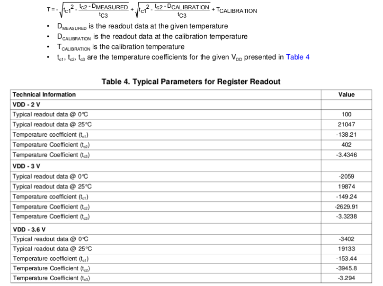
5- If you try to solve the second order equation (7) in page 6 with the coefficients in table 4 on the same page there are no real solutions for digital readings above 17800 (the decriment delta is negative)... wich is below 25oC...

I really appreciate some help

  • //******************************************************************************
    //! @file       cc120x_easy_link_rx.c
    //! @brief      This program sets up an easy link between two trxEB's with
    //!             CC112x EM's connected.
    //!             The program can take any recomended register settings exported
    //!             from SmartRF Studio 7 without any modification with exeption
    //!             from the assumtions decribed below.
    //
    //              Notes: The following asumptions must be fulfilled for
    //              the program to work:
    //
    //                  1.  GPIO2 has to be set up with GPIO2_CFG = 0x06
    //                      PKT_SYNC_RXTX for correct interupt
    //                  2.  Packet engine has to be set up with status bytes enabled
    //                      PKT_CFG1.APPEND_STATUS = 1
    //
    //  Copyright (C) 2013 Texas Instruments Incorporated - http://www.ti.com/
    //
    //  Redistribution and use in source and binary forms, with or without
    //  modification, are permitted provided that the following conditions
    //  are met:
    //
    //      Redistributions of source code must retain the above copyright
    //      notice, this list of conditions and the following disclaimer.
    //
    //      Redistributions in binary form must reproduce the above copyright
    //      notice, this list of conditions and the following disclaimer in the
    //      documentation and/or other materials provided with the distribution.
    //
    //      Neither the name of Texas Instruments Incorporated nor the names of
    //      its contributors may be used to endorse or promote products derived
    //      from this software without specific prior written permission.
    //
    //  THIS SOFTWARE IS PROVIDED BY THE COPYRIGHT HOLDERS AND CONTRIBUTORS
    //  "AS IS" AND ANY EXPRESS OR IMPLIED WARRANTIES, INCLUDING, BUT NOT
    //  LIMITED TO, THE IMPLIED WARRANTIES OF MERCHANTABILITY AND FITNESS FOR
    //  A PARTICULAR PURPOSE ARE DISCLAIMED. IN NO EVENT SHALL THE COPYRIGHT
    //  OWNER OR CONTRIBUTORS BE LIABLE FOR ANY DIRECT, INDIRECT, INCIDENTAL,
    //  SPECIAL, EXEMPLARY, OR CONSEQUENTIAL DAMAGES (INCLUDING, BUT NOT
    //  LIMITED TO, PROCUREMENT OF SUBSTITUTE GOODS OR SERVICES; LOSS OF USE,
    //  DATA, OR PROFITS; OR BUSINESS INTERRUPTION) HOWEVER CAUSED AND ON ANY
    //  THEORY OF LIABILITY, WHETHER IN CONTRACT, STRICT LIABILITY, OR TORT
    //  (INCLUDING NEGLIGENCE OR OTHERWISE) ARISING IN ANY WAY OUT OF THE USE
    //  OF THIS SOFTWARE, EVEN IF ADVISED OF THE POSSIBILITY OF SUCH DAMAGE.
    //*****************************************************************************/
    
    
    /*******************************************************************************
    * INCLUDES
    */
    #include "msp430.h"
    #include "lcd_dogm128_6.h"
    #include "hal_spi_rf_trxeb.h"
    #include "cc120x_spi.h"
    #include "stdlib.h"
    #include "cc120x_easy_link_reg_config.h"
    #include "bsp.h"
    #include "bsp_key.h"
    #include "io_pin_int.h"
    #include "bsp_led.h"
    
    
    /*******************************************************************************
    * DEFINES
    */
    #define ISR_ACTION_REQUIRED 1
    #define ISR_IDLE            0
    #define RX_FIFO_ERROR       0x11
    
    #define GPIO3               0x04
    #define GPIO2               0x08
    #define GPIO0               0x80
    
    
    /*******************************************************************************
    * LOCAL VARIABLES
    */
    //static uint8  packetSemaphore;
    static uint32 packetCounter = 0;
    
    /******************************************************************************
    * LOCAL VARIABLES
    */
    static uint32 ADCValue_I = 0;
    static uint32 ADCValue_Q = 0;
    /*******************************************************************************
    * STATIC FUNCTIONS
    */
    static void initMCU(void);
    static void registerConfig(void);
    static void runRX(void);
    static void run_MARC_debug(void);
    static void radioRxISR(void);
    static void updateLcd(void);
    static void halMcuWaitUs(uint16 usec);
    static void halMcuWaitMs(uint16 msec);
    
    
    /*******************************************************************************
    *   @fn         main
    *
    *   @brief      Runs the main routine
    *
    *   @param      none
    *
    *   @return     none
    */
    void main(void){
      uint8 RegValue = 0;
      uint8 marcState;
      // Initialize MCU and peripherals
      initMCU();
      
      // Write radio registers
      registerConfig();
      
      //Set chip in RX
      trxSpiCmdStrobe(CC120X_SRX);
      
      // Read marcstate to check state
      cc120xSpiReadReg(CC120X_MARCSTATE, &marcState, 1);
      do {
            cc120xSpiReadReg(CC120X_MARCSTATE, &marcState, 1);
        } while (marcState != 0x6D);
      
      // Enter run_MARC_debug, the chip has to be reset to resume normal functionality
      run_MARC_debug();
      
      // Read marcstate to check state
      cc120xSpiReadReg(CC120X_MARCSTATE, &marcState, 1);
      
      while(1){
        
        halMcuWaitMs(1000);
        bspLedSet(BSP_LED_1);
        cc120xSpiReadReg(CC120X_CHFILT_I2, &RegValue, 1);
        ADCValue_I = ((uint32)RegValue) << 16;
        cc120xSpiReadReg(CC120X_CHFILT_I1, &RegValue, 1);
        ADCValue_I |= (((uint32)RegValue) << 8) & 0x0000FF00;
        cc120xSpiReadReg(CC120X_CHFILT_I0, &RegValue, 1);
        ADCValue_I |= (uint32)(RegValue) & 0x000000FF;
    
        cc120xSpiReadReg(CC120X_CHFILT_Q2, &RegValue, 1);
        ADCValue_Q = ((uint32)RegValue) << 16;
        cc120xSpiReadReg(CC120X_CHFILT_Q1, &RegValue, 1);
        ADCValue_Q |= (((uint32)RegValue) << 8) & 0x0000FF00;
        cc120xSpiReadReg(CC120X_CHFILT_Q0, &RegValue, 1);
        ADCValue_Q |= (uint32)(RegValue) & 0x000000FF;
        
        updateLcd();
        ADCValue_I = 0;
        ADCValue_Q = 0;
        bspLedClear(BSP_LED_1);
      }
    }
    
    /******************************************************************************
     * @fn          run_MARC_debug
     *
     * @brief       puts radio in RX and enter MARC debug, turns off the IFAMP
     *                
     * @param       none
     *
     * @return      none
     */
    static void run_MARC_debug(void){
      uint8 txBuffer[18] = {0x0F,0x28,0x02,0x90,0x42,0x1B,0x7E,0x1F,0xFE,0xCD,0x06,0x1B,0x0E,0xA1,0x0E,0xA4,0x00,0x3F};
      uint8 writeByte;
     
       
      // Write debug init to tx fifo
      cc120xSpiWriteTxFifo(txBuffer,sizeof(txBuffer));
      // Run code from FIFO
      writeByte=0x01; 
      cc120xSpiWriteReg( CC120X_BIST, &writeByte, 1);
      // Strobe IDLE
      trxSpiCmdStrobe(CC120X_SIDLE); 
      // Set IF AMP in PD
      writeByte=0x1F;
      cc120xSpiWriteReg( CC120X_WOR_EVENT0_LSB, &writeByte, 1);
      // Strobe SXOFF to copy command over
      trxSpiCmdStrobe(CC120X_SXOFF); 
    }
    
    
    /*******************************************************************************
    *   @fn         radioRxISR
    *
    *   @brief      ISR for packet handling in RX. Sets packet semaphore
    *               and clears ISR flag
    *
    *   @param      none
    *
    *   @return     none
    */
    //static void radioRxISR(void) {
    //
    //    // Set packet semaphore
    //    packetSemaphore = ISR_ACTION_REQUIRED;
    //
    //    // Clear ISR flag
    //    ioPinIntClear(IO_PIN_PORT_1, GPIO2);
    //}
    
    
    /*******************************************************************************
    *   @fn         initMCU
    *
    *   @brief      Initialize MCU and board peripherals
    *
    *   @param      none
    *
    *   @return     none
    */
    static void initMCU(void) {
    
        // Init clocks and I/O
        bspInit(BSP_SYS_CLK_8MHZ);
    
        // Init LEDs
        bspLedInit();
    
        // Init buttons
        bspKeyInit(BSP_KEY_MODE_POLL);
    
        // Initialize SPI interface to LCD (shared with SPI flash)
        bspIoSpiInit(BSP_FLASH_LCD_SPI, BSP_FLASH_LCD_SPI_SPD);
    
        // Init LCD
        lcdInit();
    
        // Instantiate transceiver RF SPI interface to SCLK ~ 4 MHz
        // Input parameter is clockDivider
        // SCLK frequency = SMCLK/clockDivider
        trxRfSpiInterfaceInit(2);
    
        // Enable global interrupt
        _BIS_SR(GIE);
    }
    
    
    /*******************************************************************************
    *   @fn         registerConfig
    *
    *   @brief      Write register settings as given by SmartRF Studio found in
    *               cc120x_easy_link_reg_config.h
    *
    *   @param      none
    *
    *   @return     none
    */
    static void registerConfig(void) {
    
        uint8 writeByte;
    
        // Reset radio
        trxSpiCmdStrobe(CC120X_SRES);
    
        // Write registers to radio
        for(uint16 i = 0;
            i < (sizeof(preferredSettings)/sizeof(registerSetting_t)); i++) {
            writeByte = preferredSettings[i].data;
            cc120xSpiWriteReg(preferredSettings[i].addr, &writeByte, 1);
        }
    }
    
    
    /*******************************************************************************
    *   @fn         updateLcd
    *
    *   @brief      updates LCD buffer and sends buffer to LCD module
    *
    *   @param      none
    *
    *   @return     none
    */
    static void updateLcd(void){
      
          // Update LDC buffer and send to screen.
          lcdBufferClear(0);
          lcdBufferPrintString(0, "    Temp test    ", 0, eLcdPage0);     
          lcdBufferPrintInt(0, ADCValue_I, 10, eLcdPage3);
          lcdBufferPrintInt(0, ADCValue_Q, 10, eLcdPage4);
          lcdSendBuffer(0);
    }
    
    
    /***********************************************************************************
    * @fn          halMcuWaitUs
    *
    * @brief       Busy wait function. Waits the specified number of microseconds. Use
    *              assumptions about number of clock cycles needed for the various
    *              instructions. The duration of one cycle depends on MCLK. In this HAL
    *              , it is set to 8 MHz, thus 8 cycles per usec.
    *
    *              NB! This function is highly dependent on architecture and compiler!
    *
    * @param       uint16 usec - number of microseconds delay
    *
    * @return      none
    */
    
    #pragma optimize=none
    void halMcuWaitUs(uint16 usec) // 5 cycles for calling
    {
        // The least we can wait is 3 usec:
        // ~1 usec for call, 1 for first compare and 1 for return
        while(usec > 3)       // 2 cycles for compare
        {                // 2 cycles for jump
            NOP();       // 1 cycles for nop
            NOP();       // 1 cycles for nop
            NOP();       // 1 cycles for nop
            NOP();       // 1 cycles for nop
            NOP();       // 1 cycles for nop
            NOP();       // 1 cycles for nop
            NOP();       // 1 cycles for nop
            NOP();       // 1 cycles for nop
            usec -= 2;        // 1 cycles for optimized decrement
        }
    }                         // 4 cycles for returning
    
    /***********************************************************************************
    * @fn          halMcuWaitMs
    *
    * @brief       Busy wait function. Waits the specified number of milliseconds. Use
    *              assumptions about number of clock cycles needed for the various
    *              instructions.
    *
    *              NB! This function is highly dependent on architecture and compiler!
    *
    * @param       uint16 millisec - number of milliseconds delay
    *
    * @return      none
    */
    #pragma optimize=none
    void halMcuWaitMs(uint16 msec)
    {
        while(msec-- > 0)
        {
            halMcuWaitUs(1000);
        }
    }
    4353.cc120x_easy_link_reg_config.h

    See the attached code

  • It could look like the coefficients in the Design Note for some reason is off.

    I looked into the original excel sheet and the correct coefficients should be:

    2.0V: tc1: -3.7, tc2: 958, tc3: 385

    3.0V: tc1: -3.3, tc2: 992, tc3: -2630

    3.6V: tc1: -3.3, tc2: 1011, tc3: -3946

  • Thank you for your answer.

    I've set up the cc1200 according to your code (the registers in preferredSettings[]). I still have problems.

    I've tested the following things:

    1- I've used the exact code you've sent me: CC120X_CHFILT_I2 = 0x02 but all others are 0 (which is ok since CC120X_CHFILT_I2=0x02 means valid value CHFILT_STARTUP_VALID=1) but the data is 0 (useless). I also get status byte 0x60 (RX FIFO error) after cc120xSpiWriteTxFifo() in the run_MARC_debug() function.

    2- I've used the exact code you sent me but I've added a little code to flush the RX FIFO in the beginning of the run_MARC_debug() function and It get rif of the status byte = 0x60 issue above. But, the CHFILT_STARTUP_VALID bit in CC120X_CHFILT_I2 is now 0 and the digital readout is a little bit jumpy but around 130000.... 
    How do I know that the cc1200 is correctly configured and how do I use the CHFILT_Ix and CHFILT_Qx registers to get a readout that I can use to compute the temperature? Your code does not give any information about this.
    Thank you in advance
  • Thank you for your answer...

    I'll try the new coefiecients soon. I've problems configuring and reading data from the cc1200 that I'd like to solve first.

    I really want to know how to use the CC120X_CHFILT_Ix and CC120X_CHFILT_Qx to get a digital readout to use in eqation (7) on page 6?

  • For the first question: Do you check that the radio is in Rx before going into the run_MARC_debug() function?

    For the readout: It is only the I data that should be used, the Q data were just part of a debug I had.

    This part of the code:

        cc120xSpiReadReg(CC120X_CHFILT_I2, &RegValue, 1);
        ADCValue_I = ((uint32)RegValue) << 16;
        cc120xSpiReadReg(CC120X_CHFILT_I1, &RegValue, 1);
        ADCValue_I |= (((uint32)RegValue) << 8) & 0x0000FF00;
        cc120xSpiReadReg(CC120X_CHFILT_I0, &RegValue, 1);
        ADCValue_I |= (uint32)(RegValue) & 0x000000FF;

    place the digital readout used in the equation in the ADCValue_I parameter.

  • Nope, I don't check if I'm in RX-mode but my status byte is 0x10 when I set the modem in RX-mode until I try to write/execute from FIFO....

    Here is my output of the first question:

    CC120X DIGITAL READING - Reset radio [chip status 0x10]
    CC120X DIGITAL READING - Configure modem for digital temperature reading
    CC120X DIGITAL READING - Set register 0x0008 to 0xA9 [chip status 0x00]
    CC120X DIGITAL READING - Set register 0x000B to 0x0B [chip status 0x00]
    CC120X DIGITAL READING - Set register 0x000C to 0x40 [chip status 0x00]
    CC120X DIGITAL READING - Set register 0x000D to 0x2C [chip status 0x00]
    CC120X DIGITAL READING - Set register 0x000E to 0x8A [chip status 0x00]
    CC120X DIGITAL READING - Set register 0x000F to 0x00 [chip status 0x00]
    CC120X DIGITAL READING - Set register 0x0010 to 0x01 [chip status 0x00]
    CC120X DIGITAL READING - Set register 0x0011 to 0x47 [chip status 0x00]
    CC120X DIGITAL READING - Set register 0x0012 to 0x85 [chip status 0x00]
    CC120X DIGITAL READING - Set register 0x0013 to 0x8F [chip status 0x00]
    CC120X DIGITAL READING - Set register 0x0014 to 0x75 [chip status 0x00]
    CC120X DIGITAL READING - Set register 0x0015 to 0x10 [chip status 0x00]
    CC120X DIGITAL READING - Set register 0x0016 to 0x27 [chip status 0x00]
    CC120X DIGITAL READING - Set register 0x0017 to 0xEE [chip status 0x00]
    CC120X DIGITAL READING - Set register 0x001B to 0x11 [chip status 0x00]
    CC120X DIGITAL READING - Set register 0x001C to 0x94 [chip status 0x00]
    CC120X DIGITAL READING - Set register 0x001D to 0x00 [chip status 0x00]
    CC120X DIGITAL READING - Set register 0x0020 to 0x12 [chip status 0x00]
    CC120X DIGITAL READING - Set register 0x0026 to 0x00 [chip status 0x00]
    CC120X DIGITAL READING - Set register 0x0028 to 0x20 [chip status 0x00]
    CC120X DIGITAL READING - Set register 0x002E to 0xFF [chip status 0x00]
    CC120X DIGITAL READING - Set register 0x2F00 to 0x00 [chip status 0x00]
    CC120X DIGITAL READING - Set register 0x2F02 to 0x03 [chip status 0x00]
    CC120X DIGITAL READING - Set register 0x2F05 to 0x02 [chip status 0x00]
    CC120X DIGITAL READING - Set register 0x2F0C to 0x56 [chip status 0x00]
    CC120X DIGITAL READING - Set register 0x2F0D to 0xCC [chip status 0x00]
    CC120X DIGITAL READING - Set register 0x2F0E to 0xCC [chip status 0x00]
    CC120X DIGITAL READING - Set register 0x2F10 to 0xEE [chip status 0x00]
    CC120X DIGITAL READING - Set register 0x2F11 to 0x10 [chip status 0x00]
    CC120X DIGITAL READING - Set register 0x2F12 to 0x04 [chip status 0x00]
    CC120X DIGITAL READING - Set register 0x2F13 to 0x55 [chip status 0x00]
    CC120X DIGITAL READING - Set register 0x2F16 to 0x40 [chip status 0x00]
    CC120X DIGITAL READING - Set register 0x2F17 to 0x0E [chip status 0x00]
    CC120X DIGITAL READING - Set register 0x2F19 to 0x03 [chip status 0x00]
    CC120X DIGITAL READING - Set register 0x2F1B to 0x33 [chip status 0x00]
    CC120X DIGITAL READING - Set register 0x2F1D to 0x17 [chip status 0x00]
    CC120X DIGITAL READING - Set register 0x2F1F to 0x00 [chip status 0x00]
    CC120X DIGITAL READING - Set register 0x2F20 to 0x6E [chip status 0x00]
    CC120X DIGITAL READING - Set register 0x2F21 to 0x1C [chip status 0x00]
    CC120X DIGITAL READING - Set register 0x2F22 to 0xAC [chip status 0x00]
    CC120X DIGITAL READING - Set register 0x2F27 to 0xB5 [chip status 0x00]
    CC120X DIGITAL READING - Set register 0x2F2F to 0x09 [chip status 0x00]
    CC120X DIGITAL READING - Set register 0x2F32 to 0x0E [chip status 0x00]
    CC120X DIGITAL READING - Set register 0x2F36 to 0x03 [chip status 0x00]
    CC120X DIGITAL READING - Set register 0x2F9C to 0x2A [chip status 0x00]
    CC120X DIGITAL READING - Set register 0x2F9E to 0x07 [chip status 0x00]
    CC120X DIGITAL READING - Set register 0x2F2D to 0x07 [chip status 0x00]
    CC120X DIGITAL READING - Set register 0x2F96 to 0x01 [chip status 0x00]
    CC120X DIGITAL READING - Done!
    CC120X DIGITAL READING - Set modem in RX mode [chip status 0x00]
    CC120X DIGITAL READING - MARC status 0x6D [chip status 0x10]
    CC120X DIGITAL READING - Set modem in MARC debug mode
    CC120X DIGITAL READING - Wrote MARC buffer successfully
    CC120X DIGITAL READING - Run code from FIFO [chip status 0x60]
    CC120X DIGITAL READING - Set idle mode [chip status 0x60]
    CC120X DIGITAL READING - Reset IFAMP [chip status 0x60]
    CC120X DIGITAL READING - Turn off crystal oscillator [chip status 0x60]
    CC120X DIGITAL READING - MARC status 0x11 [chip status 0x60]

    Thanx

  • Are these values valid for CC1120 also?

    Because using these values, the temperature values have drastic difference w.r.t. the actual values. However, using the values in the DN403 app. note, the calculated temperature values are near to the measured values.

    Could you please clarify?

  • Is this question related to your other post or which values are you referirng to?

  • TER said:

    It could look like the coefficients in the Design Note for some reason is off.

    I looked into the original excel sheet and the correct coefficients should be:

    2.0V: tc1: -3.7, tc2: 958, tc3: 385

    3.0V: tc1: -3.3, tc2: 992, tc3: -2630

    3.6V: tc1: -3.3, tc2: 1011, tc3: -3946

    I'm referring to these values. The values in the DN403 App. Note are different from these.

    And I'm operating the CC1120 Chip at 3.3V. What will the values at that voltage?

  • As my previous mail indicate the values in the design note are wrong based on my measurements results from CC1120. If you look at the values for 3.0 and 3.6 they are more or less equal except for tc3. If you do a one point calibration the value of tc3 is to important.

  • Using the values from your earlier post on this thread, the output is erroneous. 

    Aren't the values of tc1, tc2, tc3 exchanged with other values?

    For reference:

    Please verify,

    Thanks

  • We actually need 1 other datapoint (say T=50oC and the corresponding value). We could compute tc1..tc3 ourselfes....

    May be something to consider for the next datasheet :)

  • @50 degree the typical readout is

    2.0 V: 37996

    3.0 V: 38163

    3.6 V: 37879