This thread has been locked.

If you have a related question, please click the "Ask a related question" button in the top right corner. The newly created question will be automatically linked to this question.

CC1125 SPI is not working

Other Parts Discussed in Thread: CC1125, CC1125DK, CC1120

Hello,

First of all sorry if i am repeating any previous query. I tried a lot but unable to find the solution.

I am using CC1125 Low-Power High Performance Transceiver and trying to integrate the same with ARM architecture based Controller. I already understand the code available on internet and checked connections of CS, MISO, MOSI and SCLK pins. But i am facing below mentioned issues:

1) As suggested, inserting the CS in low mode and waiting for MISO to get zero. After doing the same i am sending the strobe command at address 0x30 to reset the chip. Where i have to receive 0x0F, i am getting 0x00 as the response.

2) After this sending the Write command as  in CC1125 code. But after writing, during reading not getting any value.

I checked the signals on DSO as well, SCLK is coming and MOSI is also sending the data but not getting any response.

Please update that which mode is required - TI or Motorola?

Initially i am using Motorola mode because as per my understanding in CC1125 CPOL = 0, CPHA = 0 mode is used.

I need the answer on urgent basis, please try to respond asap.

Thanks in advance,

Salil

  • Salin, 

    Please refer to page 7 of the User Guide.

    http://www.ti.com/lit/ug/swru295e/swru295e.pdf

    It says data is clocked on possitive edge of the Clock signal.

    Regards,
    /TA

  • Hello,

    Thanks for your mail. Can you please elaborate it more because i am not able to understand your point.

    As mentioned by you, already studied the User Manual.  

    For this mode - CPOL = 0 means CK to 0 when idle

                                 CPHA = 0 means the first clock transition is the first data captured edge

    And i am using Motorola SPI at place of TI SPI.

    Regards

    Salil

  • - Do you use a CC1125 EM or your own hardware?

    - Could you send us a plot showing the SPI communication?

    - The UserGuide shows how how the SPI communication looks like. Align your MCU settings no comply with this.

  • Hello,

    We are using CC1125 EM and now its working.

    Main problem was, i was using Motorola SPI mode.

    Now  i used TI SPI mode and its working.

    Thanks 

  • Hello,

    I had modified the easy link code to run on an ARM core controller. I was able to send packets, but could not receive any packets. 

    Then I tried to run the original Easy link code on the TRxEB (+CC1125.) I was getting the same problem.

    I have ensured that the GPIO2_CFG value is 0x06. 

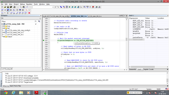
    I also tried to debug the code and it was getting stuck due to the value of the variable packetSemaphore not changing to 1.

    Is it the PKT_SYNC_RXTX status signal not asserting on GPIO 2? If so why?

    My register values in the receiving code are as follows:

    {CC112X_IOCFG3,            0xB0},
    {CC112X_IOCFG2,            0x06},
    {CC112X_IOCFG1,            0xB0},
    {CC112X_IOCFG0,            0xB0},
    {CC112X_SYNC_CFG1,   0x0B},
    {CC112X_DCFILT_CFG,  0x1C},
    {CC112X_IQIC,                   0xC6},
    {CC112X_CHAN_BW,        0x08},
    {CC112X_MDMCFG0,         0x05},
    {CC112X_AGC_REF,          0x20},
    {CC112X_AGC_CS_THR,  0x19},
    {CC112X_AGC_CFG1,        0xA9},
    {CC112X_AGC_CFG0,        0xCF},
    {CC112X_FIFO_CFG,           0x00},
    {CC112X_SETTLING_CFG, 0x03},
    {CC112X_FS_CFG,                0x12},
    {CC112X_PKT_CFG1,            0x05},
    {CC112X_PKT_CFG0,            0x20},
    {CC112X_PA_CFG2,               0x4F},
    {CC112X_PA_CFG1,                0x56},
    {CC112X_PA_CFG0,                0x1C},
    {CC112X_PKT_LEN,                 0xFF},
    {CC112X_IF_MIX_CFG,             0x00},
    {CC112X_FREQOFF_CFG,       0x22},
    {CC112X_FREQ2,                      0x6C},
    {CC112X_FREQ1,                       0x80},
    {CC112X_FREQ0,                       0x00},
    {CC112X_FS_DIG1,                    0x00},
    {CC112X_FS_DIG0,                     0x5F},
    {CC112X_FS_CAL0,                     0x0E},
    {CC112X_FS_DIVTWO,                0x03},
    {CC112X_FS_DSM0,                     0x33},
    {CC112X_FS_DVC0,                     0x17},
    {CC112X_FS_PFD,                        0x50},
    {CC112X_FS_PRE,                        0x6E},
    {CC112X_FS_REG_DIV_CML,     0x14},
    {CC112X_FS_SPARE,                    0xAC},
    {CC112X_XOSC5,                            0x0E},
    {CC112X_XOSC3,                            0xC7},
    {CC112X_XOSC1,                             0x07},

    Here is a screen shot of the code in debugging session (the pointer is at the line where it is stuck)

  • By first look the settings you are using are for a 32 MHz crystal, the CC1125 EM most likely using a 40 MHz crystal.

  • Thanks for your reply.

    But we checked with Smart RF Studio and our registers are set for 40MHZ not for 32MHZ.

  • {CC112X_FREQ2,                      0x6C},
    {CC112X_FREQ1,                       0x80},
    {CC112X_FREQ0,                       0x00},

    Gives a RF frequency equal to 1085 MHz with 40 MHz crystal but 868 MHz with 32 MHz. I assumed you wanted 868 MHz?

  • Hello,

    Initially the issue is different. Please try to understand.

    Point is - Currently i am using  original Easy link code available on web to run on the TRxEB (+CC1125.)

    I didn't change anything in code and still not able to receive the data whereas previously it was working.

    Is this issue is related to hardware?

    ( I purchased CC1125 development kit  for testing(http://www.ti.com/tool/cc1125dk).Downloaded the easy link code from net and tested the same on this kit. It was working and i was able to receive the data. Then i used CC1125EM board with ARM based controller. SPI was working but not able to receive the data. To see the issues i again tested the CC1125EM board with SmartRF Transceiver EB (TrxEB) and then same problem occurred in  this kit as well.)

  • The Easymode code is for CC1120 with a 32 MHz clock. You have to change the frequency dependent registers for this to work, 1085 MHz is outside the supported band of the chip. Use SmartRF Studio and change from 32 MHz to 40 MHz to see which registers you have to adjust. Note that one of the ADC registers also has to be changed.