This thread has been locked.

If you have a related question, please click the "Ask a related question" button in the top right corner. The newly created question will be automatically linked to this question.

wireless output setting of CC1200

Genius 5960 points
Other Parts Discussed in Thread: CC1200

I want to confirm the settings: [0 5] PA_CFG1.

I am using the SmartRF Studio and CC1200.
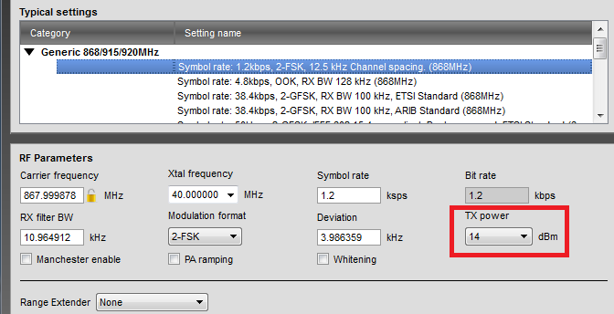
 

In SmartRF GUI on,

The value of "Register View" when you enter a value in the "TX power"

The value of "TX power" when you put the value at "Register View"

I summarizes the results in the case of.

3146.PA_CFG1.xls


For example,

If you enter "TX Power" = 6dBm, Become "Register View" = 0x2C. ("calculation result" = 0x2F)

If you enter "Regster View" = 0x2F Become "TX Power" = 6dBm.

Which is correct?

Best Regards,

hamada

  • When you enter a value in "TX Power" the register setting is taken from the CC1200 characterization. As an example, when entering "6 dBm" the register setting is 0x2C because +6 dBm was the measured value for this register setting when characterizing the chip.

    If you enter the a value in "Register View", the output power is calculated. As you correctly point out, the calculation does not match the measured values and only gives an approximation.

    Use the "TX power" values in "Normal View" to get the output power setting to use for you application.

  • Hi, Sverre.

    Thank you for reply.

    I can not "normal view"

    Are you sure that the attached?

    Set the value that was output to the "TX Power",

    How should I use to design its register value?

    Best Regards,

    hamada

  • Sorry, I used an old term when referring to "Normal View". The picture you attached is what I mean by "Normal View".

    To get the right register settings for a given TX power, choose one of the options from the "TX power" pull-down menu. The PA_CFG register settings will then be set according to the values we found during the chip characterization.