This thread has been locked.

If you have a related question, please click the "Ask a related question" button in the top right corner. The newly created question will be automatically linked to this question.

CC1110+CC1190 Design Issue

Other Parts Discussed in Thread: CC1190, CC1101

Dear Ti,

we designed Two custom boards with Ti reference Design.

One Board is designed with the reference of CC1110EM 868 and 915MHz Reference Design 

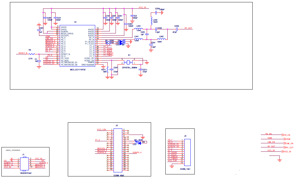
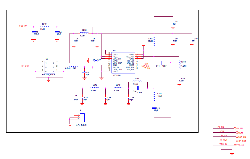
and Second Board is Designed with the combination of CC1110-CC1190 wih reference of CC1101-CC1190EM 869 MHz Reference Design 

please find the attached second board design schematics file1 & 2. 

we purchase two range extender EM modules of CC1101-CC1190EM 869 MHz and we have established communication between PC to PC using CCdebugger, one as Transmitter and second as Receiver.

we achieved range 350 to 400 meters in Line Of Site.

the same range we want to get with the our custom boards one and two but we are unable to get more than 10 meters distance(range).

queries:

1) is there any mistakes we followed with reference designs ?

2) How we can achieve the distance more than 500 meters in LOS with our custom boards ?

3) our target is to achieve more than 150 meters is Non Line of site in any environment and more than 500 meters is Line of site . is there any other solutions to achieve our target ?

in our application one device is a sleeping End Device (Transmitter) and second device is Access point ( Receiver ) 24/7 power on device.

waiting for your valuable information.

  • In cases like this you should try to find out if the issue is on the Rx or Tx side and if the issue is related to the antenna. Are you able to run conducted tests to check output power and sensitivity on your board?
  • Hi TER,

    Thanks for your Replay.

    I have conducted test between CC1101-CC1190EM 869 MHz EM Boards and in Smart RF studio It is able to detect and i am able to see the sensitivity and power levels .

    I have not conducted test between our custom boards.

    But when i connect one our range extender custom board to PC using CC debugger after when i open Smart RF studio panel it is showing detected CC1110 IC but when i enter into a control panel I am unable to select range Extender CC1190 to select the frequency range and for setting the power levels.

    few more queries:
    1) is this must to use range extender IC CC1190 with the combination of CC1110 in both the end (Transmitter & Receiver) or is there any possible to use any other End (either at Transmitter side or at Receiver side) ?
    2)CC1101 is a transceiver and CC1110 is an MCU, is there any schematic change do we need to do, if we combine CC1110+CC1190 with reference of CC1101+CC1190 ?
    3) what is the proven range of Range extender with the Combination of CC1110+CC1190 & CC1101+Cc1190 in different environment (LOS & NLOS) and please share the details regarding the above ?

    waiting for your valuable information.
  • I was asking about about either conducted sensitivity tests or conducted output power tests. Conducted between the boards has no real value.

    When starting to debug you need to know if it's the transmitter or the receiver (or both) that have poor performance. Have you checked that the control signals for CC1190 is set correctly?

    1) Depends about the required link budget you need. In Rx CC1190 gives about 3 dB improved link budget, Tx gives up to 12 dB. Use the excel sheet in this post  to calculate the needed total link budget for the range you want to have.

    2) No. It should be to replace CC1101 with CC1110. I haven't double checked the component values in your schematic but it looks correct.