I have another problem related with TX power. I have assambled 6 RF PCB and all of them behave the same:
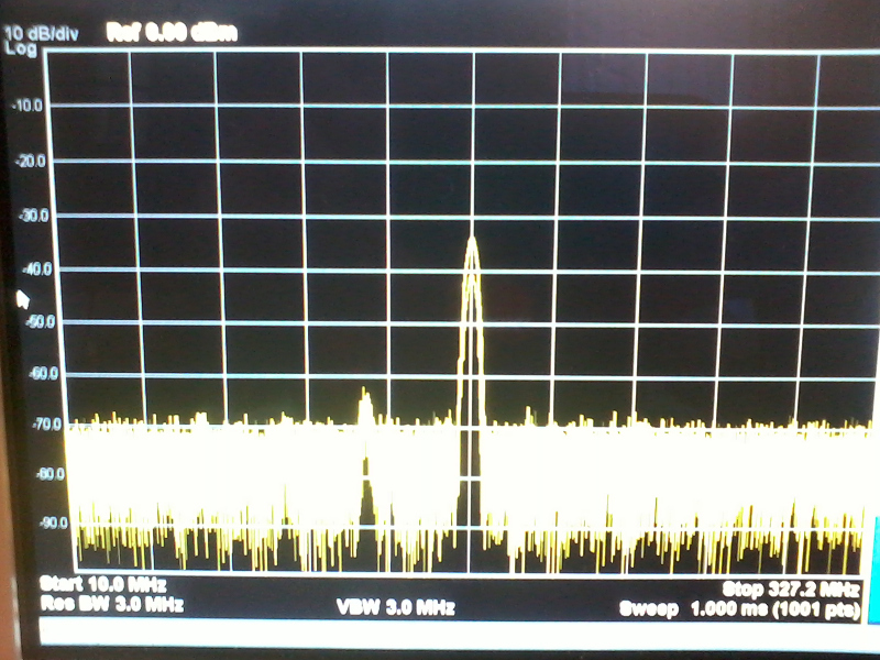
For TX output power @ 0dBm the signal on signal analyzer is down to -35dBm
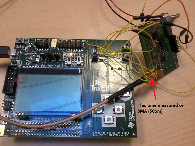
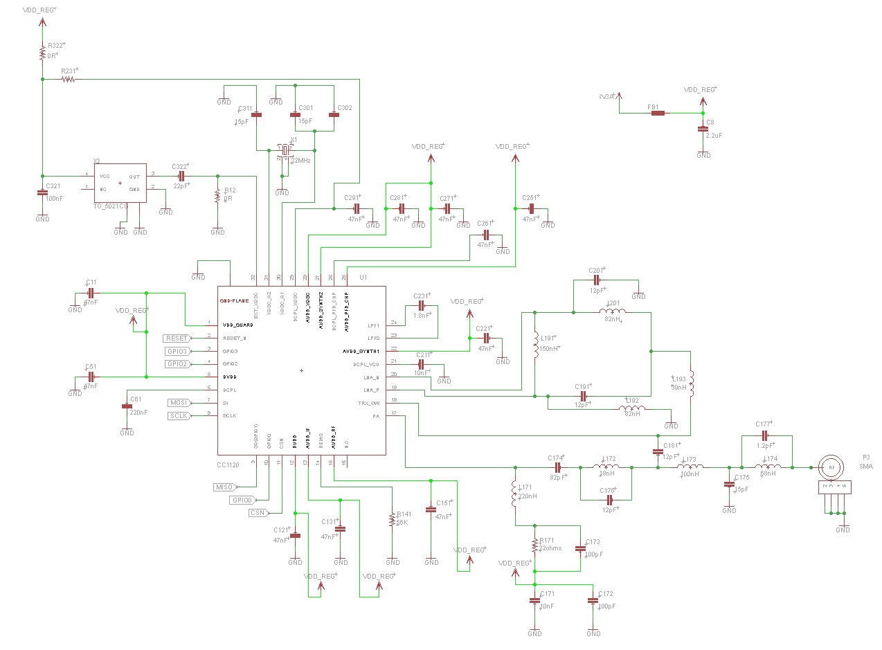
I decide to check if there is something wrong with filter so I remove C174 (see below)
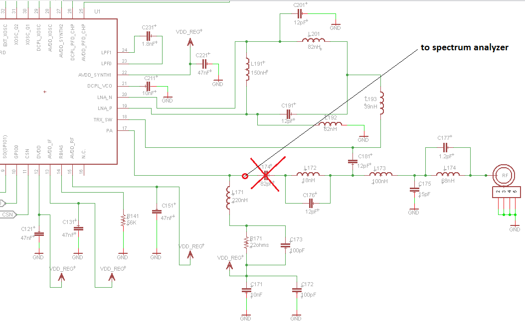
and measure signal on spectrum from that place (C174)
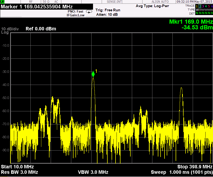
To transmitt at 0dBm I set registers:
{CC112X_PA_CFG2, 0x5D}
Resulting in output power - 34.53:
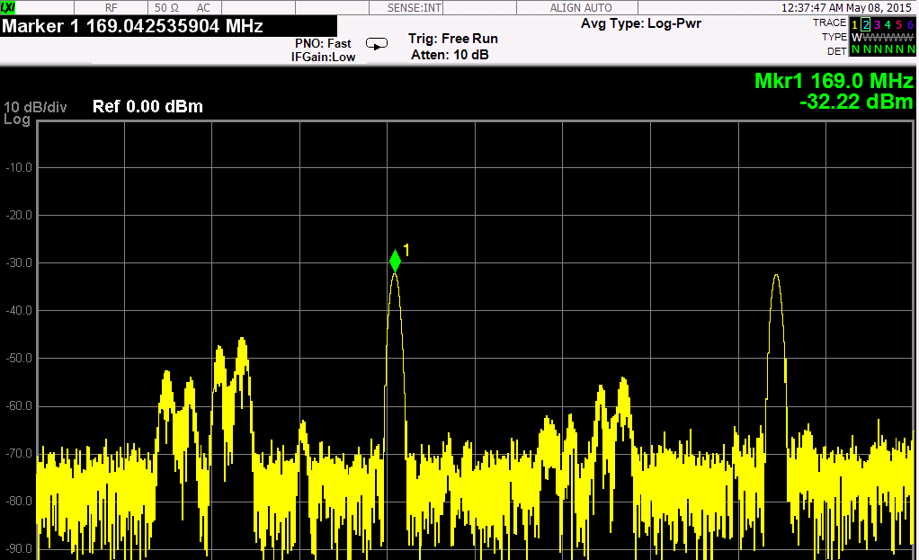
To transmitt at +15dBm I set registers:
{CC112X_PA_CFG2, 0x7F}
Resulting in output power - 32dBm:
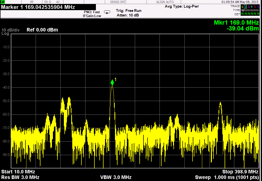
To transmitt at +15dBm I set registers:
{CC112X_PA_CFG2, 0x43}
Resulting in output power - 40dBm:
Is this software problem? Are there extra registers that need to be change.
When I change
//{CC112X_PA_CFG1, 0x56}, // test output power
//{CC112X_PA_CFG0, 0x7C}, // test output power
There is no significant change in power.