Hi,
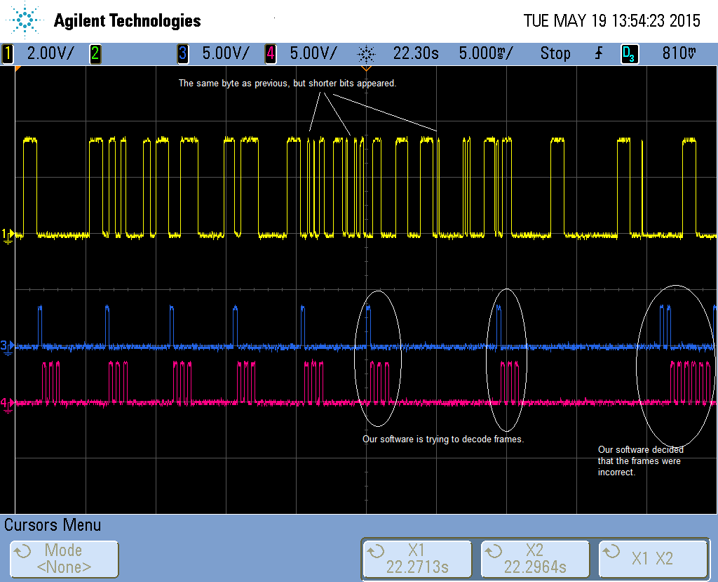
We are using CC1101 with MSP430F5xxx to communicate with “strange” device. We send a question and the device sends a response. It is always the same question, and the answer also should be the same. But randomly we receive incorrect data. On oscilloscope it looks like additional bit/bits appears in receiving frames. They don’t look like glitches nor jitters – just shorter bits.
We work on 433MHz; use asynchronous serial mode; 2,4kbd; RX filter BW=200kHz; 2-FSK modulation; deviation 6,3kHz. Below all our register settings.
We have another transceiver which work properly all the time and that’s why we assume that “strange” device always responses in the same way. We have tried many other registers settings, used another CC1101 module, antennas, tried to incorporate pull-ups, pull-downs and RC filters on uart lines and a few other things, but with no luck. And we don’t know what to do else.
Maybe someone faced with similar problem or registers settings are wrong? We ask for help with our problem.
Thanks in advance.
// Rf settings for CC1101
const RF_SETTINGS g_CC1100RFSettingsItron =
{
0x0D, // IOCFG2 GDO2 Output Pin Configuration-
0x2E, // IOCFG1 GDO1 Output Pin Configuration
0x2D, // IOCFG0 GDO0 Output Pin Configuration-
0x07, // FIFOTHR RX FIFO and TX FIFO Thresholds
0xD3, // SYNC1 Sync Word, High Byte
0x91, // SYNC0 Sync Word, Low Byte
0xFF, // PKTLEN Packet Length-
0x04, // PKTCTRL1 Packet Automation Control-
0x32, // PKTCTRL0 Packet Automation Control-
0x00, // ADDR Device Address-
0x00, // CHANNR Channel Number-
0x06, // FSCTRL1 Frequency Synthesizer Control-
0x00, // FSCTRL0 Frequency Synthesizer Control-
0x10, // FREQ2 Frequency Control Word, High Byte
0xAF, // FREQ1 Frequency Control Word, Middle Byte
0x78, // FREQ0 Frequency Control Word, Low Byte
0x86, // MDMCFG4 Modem Configuration-
0x83, // MDMCFG3 Modem Configuration-
0x04, // MDMCFG2 Modem Configuration-
0x22, // MDMCFG1 Modem Configuration-
0xF8, // MDMCFG0 Modem Configuration-
0x20, // DEVIATN Modem Deviation Setting-
0x07, // MCSM2 Main Radio Control State Machine Configuration
0x30, // MCSM1 Main Radio Control State Machine Configuration
0x18, // MCSM0 Main Radio Control State Machine Configuration-
0x16, // FOCCFG Frequency Offset Compensation Configuration-
0x6C, // BSCFG Bit Synchronization Configuration-
0x07, // AGCCTRL2 AGC Control-
0x47, // AGCCTRL1 AGC Control-
0x91, // AGCCTRL0 AGC Control-
0x87, // WOREVT1 High Byte Event0 Timeout
0x6B, // WOREVT0 Low Byte Event0 Timeout
0xF8, // WORCTRL Wake On Radio Control
0x56, // FREND1 Front End RX Configuration-
0x10, // FREND0 Front End TX Configuration-
0xE9, // FSCAL3 Frequency Synthesizer Calibration-
0x2A, // FSCAL2 Frequency Synthesizer Calibration-
0x00, // FSCAL1 Frequency Synthesizer Calibration-
0x1F, // FSCAL0 Frequency Synthesizer Calibration-
0x41, // RCCTRL1 RC Oscillator Configuration
0x00, // RCCTRL0 RC Oscillator Configuration
0x59, // FSTEST Frequency Synthesizer Calibration Control
0x7F, // PTEST Production Test
0x3F, // AGCTEST AGC Test
0x81, // TEST2 Various Test Settings-
0x35, // TEST1 Various Test Settings-
0x09, // TEST0 Various Test Settings-
};