


Hi
Can anyone help to solve CC1125 CCA Interrupt problem?
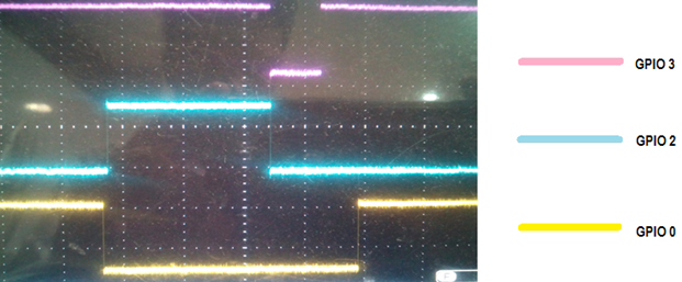
I'm testing LBT. I Configured AGS_CS_THR = 0x12, LBT option is enabled in PKT_CFG2 register and Configured GPIO3 for CCA interrupt (GPIO3 = 0x0F(15)) and GPIO2 for Packet TX/RX interrupt (GPIO2 = 0x06)
I've done the following steps before transmission.
1. Filling TXFIFO
2. Sending SRX Strobe
3. Checking whether RSSI valid or not
4. Monitoring MARC_STATUS0 register.
5. If the RSSI is valid then sending STX Strobe
I observed the both GPIO3 and GPIO0 pins are in High state only. Whenever the packet is receiving that time only it is going to Low state. then again back to High state.
Why these two GPIO pins are always in high state? I didn't get what is the problem?
I have attached the image for your reference.
Please give your valuable solution to solve this issue.
regards,
Vinoth M.
