This thread has been locked.

If you have a related question, please click the "Ask a related question" button in the top right corner. The newly created question will be automatically linked to this question.

Problem with receiving data with CC1200

Other Parts Discussed in Thread: CC1200

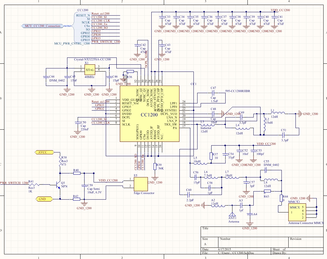
Hi, I am debugging CC1200 part in my board and I used the schematic of the CC120x EM board. Right now, I am able to send data from my custom board to an evaluation board, but it can received data from evaluation board. So I wonder if it is possible that the the circuits which are not RF part that make it not able to receive, for example the filter caps and bias resistors.  Thanks!

  • If I read your post correctly you can send but not receive.

    Have you tried to measure the output power and sensitivity? Have you tried to check the RSSI in receive to see if you manage to get increased energy in the channel when you turn on your transmitter?

    Settings: What settings do you use? If you have a small RX BW have you tried to increase this?

    Software: Do you know your software works as it should? Try using SmartRF Studio to control the CC1200 on your board.

    Hardware: To be able to comment I need to see the schematic/ layout of the CC1200 part of your design

  • Hi,

        Sorry for replying so late.  I checked the CC120X_RSSI0 and CC120X_RSSI1 register, the CC120X_RSSI0 is always 0x00, CC120X_RSSI1 is always 0x80, no matter the transmitter is on or off. 

        The program I used is the cc120x_easy_link code provided by TI. And it works for the EXP430F5438 board with CC120xEM 868/930MHz. and the schematic of my board is exactly the same with these two boards. Do you have any idea how to test it?

    Thanks

    Yi 

  • From this it sounds like a hardware issue. Please post the schematic for your board.
  • Hi, below is the schematic. I tested the pin14 and the voltage of my prototype board and the experiment board is 1.78V and 1.26V respectively.

  • I can't see anything obviously wrong on the schematic. But if pin 14 is not 1.25 V then the chip hasn't started up correctly. The only reason I can see for this is that something isn't powered as it should. Is the die paddle properly connected to ground and is the voltage level on the other pins as expected?
  • Hi, now the pin 14 is 1.25V, but the voltage of the pin 26 and pin 21 are 0.558V but the voltage of the pin 26 and pin 21 on evaluation board are 1.41V and 1.87V.

  • I tested it again, now the voltages of pin26 and pin 21 are nearly 0 V
  • But I can get the 868MHz signal from pin 26 and pin 21 once I turn on the transimitter
  • You should have about 1.8 V on pin 21 and pin26 when the chip is in Tx or Rx.