This thread has been locked.

If you have a related question, please click the "Ask a related question" button in the top right corner. The newly created question will be automatically linked to this question.

CC1125 Carrier Frequency

Other Parts Discussed in Thread: CC1125, CC1190

Hi,
Can anyone help me to solve carrier frequency issue in CC1125?

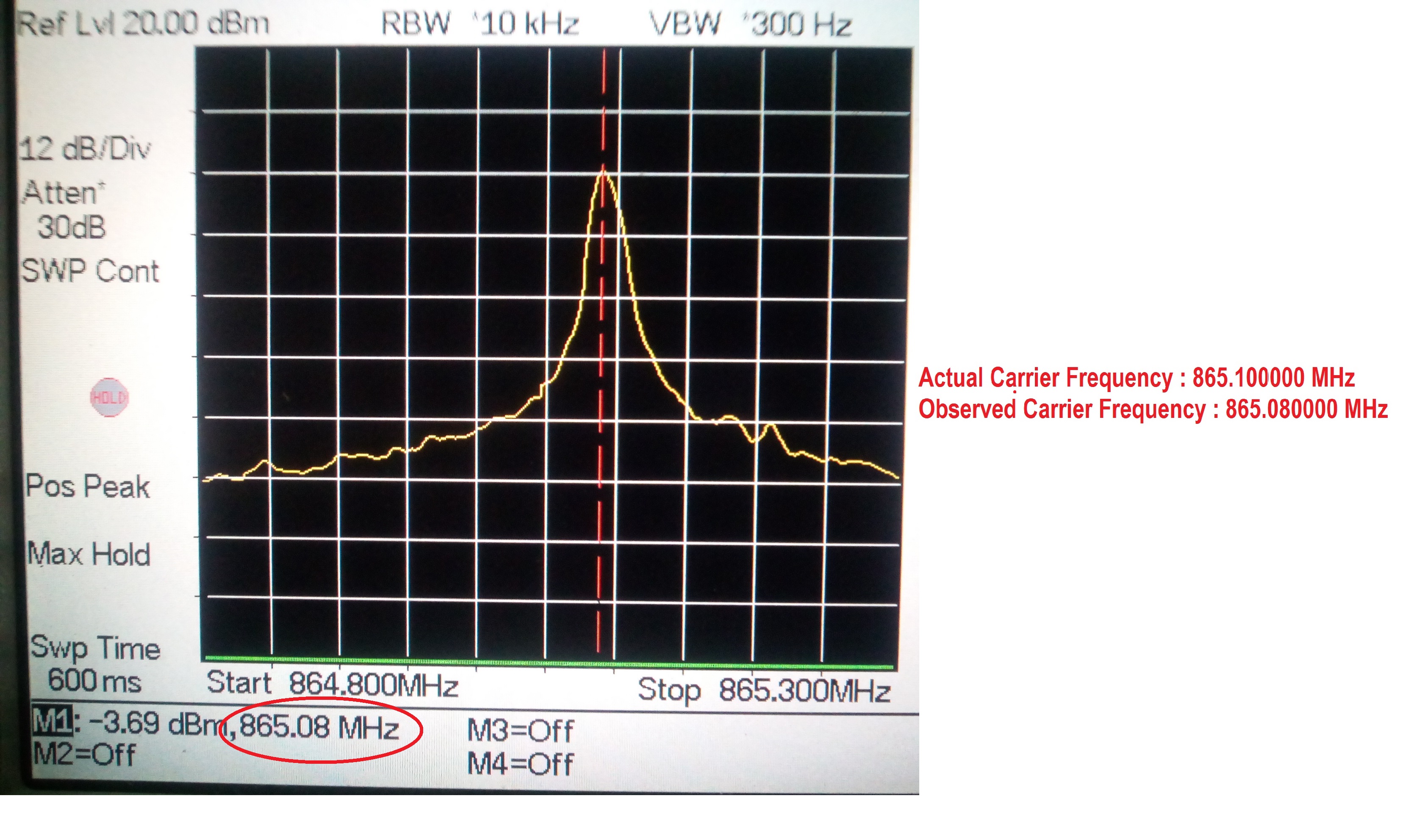
We are using CC1125 Transceiver in our own custom design board. I configured the radio to work on 865 MHz carrier frequency and I observed the peak signal in spectrum analyzer. The peak signal is on 864.99 to 864.98 (10 to 20 KHz difference). It is drifting between 864.99 MHz to 864.98 MHz and sometimes 865 MHz also.

I configured the carrier frequency registers as FREQ2 = 0x6C, FREQ1 = 0x20, FREQ20 = 0x00 for 865 MHz because we are using 32MHz Oscillator. I am not getting the peak signal continuously at exact 865 MHz and Why this variation?

Is it acceptable or not?
If not, what could be the reason?

Thanks in advance.

regards,
Vinoth M.

  • - What is the RBW when you are doing your measurements?
    - Do you have some spectrum plots showing what you are seeing?

    The frequency should not have this variation.
  • Hi TER,

    Thanks for your response.

    Q: What is the RBW when you are doing your measurements?

    A: RBW in code is 40 KHz. and RBW in Spectrum Analyzer is 10 KHz..

    Q: Do you have some spectrum plots showing what you are seeing?

    A: I don't have image for the above scenario. But I have image for 865.100000 MHz testing. I configured the radio to work on 865.100000 MHz carrier frequency. The peak signal is on 865.08 MHz. (20KHz difference).

    I configured the carrier frequency registers as FREQ2 = 0x6C, FREQ1 = 0x23, FREQ0 = 0x33 for 865.100000 MHz

    I have attached the image. Please let me know if modification is require.

    regards,

    Vinoth M.

  • You will not be able to accurately measure frequency if you set RBW = 10 kHz. Try to set it to 300 Hz and use a place marker at peak to ensure you find the peak. As an alternative use a small span.
  • Hi TER,

              Thanks for your response.

    Presently I don’t have the spectrum analyzer to do measurements. Once I complete my measurements I'll let you know.

    Now I am facing problem when I test 6 radios . I hope you will guide me to resolve this solve.

    Test scenario:

    1. Total 3 pairs. Each pair is working on different frequency.
    2. Continuous TX and RX for every 300 milli seconds.
    3. 50 kHz Channel spacing between one pair.
    4. Output power is 400mW (We are using CC1190 Power Amplifier).

    Problems:

    1. Two pairs working fine while continuous tested up to 48 hours.

    2. If I add third pair problem observed in previous working pair as well as third pair also.

                    -> Sometimes I am getting junk or corrupted data.

    3. If I receive the junk data once, it remains up to 30 seconds.

    4. I have tested with different power levels (With minimum 10mW TX power also tested) still the same exists.

    I have attached the image of my test setup.

    regards

    Vinoth M.

  • Which datarate etc do you use? Difficult to say without knowing.


    I have to correct my previous answer somewhat. Your RF frequency will be a function of your reference. If you have a 10 ppm xtal your RF frequency could be between 865 MHz +/- 8650 Hz. With 50 kHz channel spacing one pair on 865 MHz could risk blocking the pair on 865.05 MHz dependent on the datarate and RX BW used.

  • Hi TER,

    Thanks for your response.

    We are using 10ppm xtal. I have tested the both 19.2 kbps and 9.6 kbps data rates.

    The following parameters are used for 19.2 kbps data rate

    Data rate 19.2 kbps

    Deviation 3.997803 kHz

    RX Filter BW 40 kHz

    Mod Format 2-FSK

    The following parameters are used for 9.6 kbps data rate

    Data rate 9.6 kbps

    Deviation 3.997803 kHz

    RX Filter BW 25 kHz

    Mod Format 2-FSK

    The problem remains same for both data rates.

    regards,

    Vinoth M.

  • Hi TER,

    Thanks for your response.

    We are using 10ppm xtal. I have tested the both 19.2 kbps and 9.6 kbps data rates.

    The following parameters are used for 19.2 kbps data rate

       Data rate : 19.2 kbps

       Deviation : 3.997803 kHz

       RX Filter BW : 40 kHz

       Mod Format : 2-FSK

    The following parameters are used for 9.6 kbps data rate

       Data rate : 9.6 kbps

       Deviation : 3.997803 kHz

       RX Filter BW : 25 kHz

       Mod Format : 2-FSK

    The problem remains same for both data rates.

    regards,

    Vinoth M.

  • I would have expected it to be a difference between 10 mW and 400 mW and the lowest and highest RX BW.

    If you have communication between the two meters with address 1, do you see a difference if you turn on the meter with address 2 and address 3?

    If you measure RSSI in the different positions, what is the RSSI if the meter you want to communicate with is on vs one of the others?

    It sounds like a blocking issue but then you should have seen some difference between the cases.