This thread has been locked.

If you have a related question, please click the "Ask a related question" button in the top right corner. The newly created question will be automatically linked to this question.

CC1101 asynchronous tx deviation

Other Parts Discussed in Thread: CC1101

Hi guy,

im using a cc1101 in asynchronous serial mode. Im using this configuration:

RF_SETTINGS code rfSettings = {
    0x0B,  // IOCFG2          GDO2 Output Pin Configuration
    0x0C,  // IOCFG0          GDO0 Output Pin Configuration
    0x47,  // FIFOTHR         RX FIFO and TX FIFO Thresholds
    0x32,  // PKTCTRL0        Packet Automation Control
    0x06,  // FSCTRL1         Frequency Synthesizer Control
    0x10,  // FREQ2           Frequency Control Word, High Byte
    0xB1,  // FREQ1           Frequency Control Word, Middle Byte
    0x21,  // FREQ0           Frequency Control Word, Low Byte
    0xF7,  // MDMCFG4         Modem Configuration
    0x93,  // MDMCFG3         Modem Configuration
    0x30,  // MDMCFG2         Modem Configuration
    0x00,  // MDMCFG1         Modem Configuration
    0x00,  // MDMCFG0         Modem Configuration
    0x15,  // DEVIATN         Modem Deviation Setting
    0x18,  // MCSM0           Main Radio Control State Machine Configuration
    0x14,  // FOCCFG          Frequency Offset Compensation Configuration
    0x04,  // AGCCTRL2        AGC Control
    0x10,  // AGCCTRL1        AGC Control
    0x50,  // AGCCTRL0        AGC Control
    0xFB,  // WORCTRL         Wake On Radio Control
    0x11,  // FREND0          Front End TX Configuration
    0xE9,  // FSCAL3          Frequency Synthesizer Calibration
    0x2A,  // FSCAL2          Frequency Synthesizer Calibration
    0x00,  // FSCAL1          Frequency Synthesizer Calibration
    0x1F,  // FSCAL0          Frequency Synthesizer Calibration
    0x81,  // TEST2           Various Test Settings
    0x35,  // TEST1           Various Test Settings
    0x09,  // TEST0           Various Test Settings
    0x14,  // VERSION         Chip ID
    0x80,  // RSSI            Received Signal Strength Indication
    0x01,  // MARCSTATE       Main Radio Control State Machine State
    0x94,  // VCO_VC_DAC      Current Setting from PLL Calibration Module
};

paTable = { 0xC0, 0x12 } 

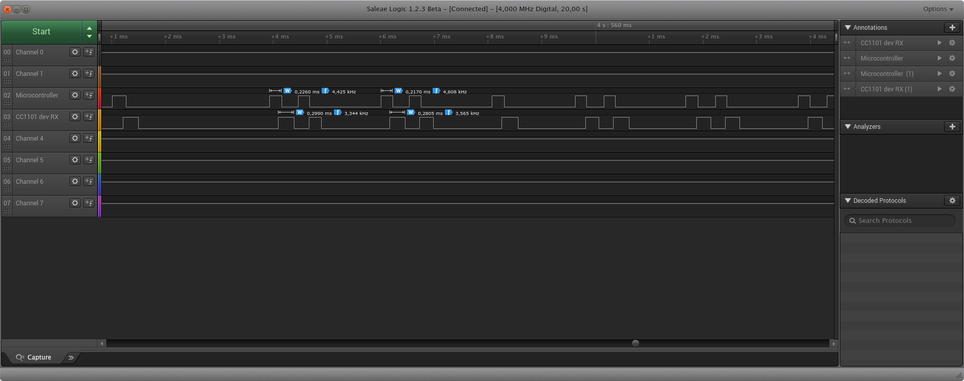
im generating a very precise signal from the microcontroller to the asynchronous tx signal. i've already checked the output signal of the microcontroller and the signal is fine. but when i use a 433Mhz receiver connected to a logic analyzer the signal shows some deviation. 

I just want to get the exact mcu output signal to be generated. I really have no idea where the davation is coming from. I tried different baudrates but that doesnt seem to have any effect on the precision. The configuration is ment to be used for controlling remote switches (kaku) etc. 

I also use the cc1101 for receiving. i use a input capture timer from the microcontroller. This makes it important that only, and only when someone is transmitting a signal, the signal gets generated onto the asynchronous rx.

Does somebody has any idea where the deviation is coming from? 

Great thanks!

  • Could you please define what you mean by deviation and how you measure it? Also how much deviation you see?
  • im measuring the CC1101's async tx (from cc1101 -> mcu) with a logic analyzer. What i mean by deviation is the difference in length in transitions of several repeating signals from my remote control. when i compare the output of the cc1101 with the signal output of a passive rx receiver the repeating signals seems to stay the same.
  • You say you measure CC1101 -> mcu. If you are using async tx the communication would go from mcu -> CC1101? Which pin have you connected the logic anal. to? Please provide plots of what you are seeing.
  • It has been a while now, unfortunately i had to work on a other project. My apologies for that.

    We are using the CC1101 as a generic receiver as well as a generic transmitter. We therefore chose to use the asynchronous serial mode for both rx and tx. Both the GD0 and GD02 pins are connected to an microcontroller. Both mcu gpio's are timer gpio's. The tx timer generates arbitrary signals while the rx gpio captures received signals both coming from the CC1101.

    Lets take a look at the pictures in the attachment:

    This is a print screen taken from a logic analyzer.

    - The Microcontroller measurement (channel 3) represents the direct tx output to the GD0 input of the CC1101 (in TX mode)

    -  The CC1101 dev RX measurement (channel 4) represents the direct rx from the GDO2 output of the  CC1101 dev kit's  (in RX Mode).

    Both CC1101's uses the same configuration. Although, 1 CC1101 is in asynchronous tx and the other is in asynchronous rx.

    As you can see, there is a significant deviation between both signals. The ideal situation would be that the microcontroller measurement is exactly the same as the CC1101 dev RX measurement. Is there anything in my configuration that you can find below that i can tweak to make this performance better?

    I've tried multiple distances, but it doesnt make any difference. i also mentioned that the CC1101 randomly has noise when rx'ing. This probably has something to do with the surrounding noise.

    The configuration i use:

    0x0D,  // IOCFG2              GDO2 Output Pin Configuration
         0x2E,  // IOCFG1              GDO1 Output Pin Configuration
         0x0D,  // IOCFG0              GDO0 Output Pin Configuration
         0x47,  // FIFOTHR             RX FIFO and TX FIFO Thresholds
         0xD3,  // SYNC1               Sync Word, High Byte
         0x91,  // SYNC0               Sync Word, Low Byte
         0xFF,  // PKTLEN              Packet Length
         0x04,  // PKTCTRL1            Packet Automation Control
         0x32,  // PKTCTRL0            Packet Automation Control
         0x00,  // ADDR                Device Address
         0x00,  // CHANNR              Channel Number
         0x06,  // FSCTRL1             Frequency Synthesizer Control
         0x00,  // FSCTRL0             Frequency Synthesizer Control
         0x10,  // FREQ2               Frequency Control Word, High Byte
         0xB1,  // FREQ1               Frequency Control Word, Middle Byte
         0x21,  // FREQ0               Frequency Control Word, Low Byte
         0xF7,  // MDMCFG4             Modem Configuration
         0x93,  // MDMCFG3             Modem Configuration
         0x30,  // MDMCFG2             Modem Configuration
         0x00,  // MDMCFG1             Modem Configuration
         0x00,  // MDMCFG0             Modem Configuration
         0x15,  // DEVIATN             Modem Deviation Setting
         0x07,  // MCSM2               Main Radio Control State Machine Configuration
         0x0C,  // MCSM1               Main Radio Control State Machine Configuration
         0x18,  // MCSM0               Main Radio Control State Machine Configuration
         0x14,  // FOCCFG              Frequency Offset Compensation Configuration
         0x6C,  // BSCFG               Bit Synchronization Configuration
         0x04,  // AGCCTRL2            AGC Control
         0x10,  // AGCCTRL1            AGC Control
         0x50,  // AGCCTRL0            AGC Control
         0x87,  // WOREVT1             High Byte Event0 Timeout
         0x6B,  // WOREVT0             Low Byte Event0 Timeout
         0xFB,  // WORCTRL             Wake On Radio Control
         0x56,  // FREND1              Front End RX Configuration
         0x11,  // FREND0              Front End TX Configuration
         0xE9,  // FSCAL3              Frequency Synthesizer Calibration
         0x2A,  // FSCAL2              Frequency Synthesizer Calibration
         0x00,  // FSCAL1              Frequency Synthesizer Calibration
         0x1F,  // FSCAL0              Frequency Synthesizer Calibration
         0x41,  // RCCTRL1             RC Oscillator Configuration
         0x00,  // RCCTRL0             RC Oscillator Configuration
         0x59,  // FSTEST              Frequency Synthesizer Calibration Control
         0x7F,  // PTEST               Production Test
         0x3F,  // AGCTEST             AGC Test
         0x81,  // TEST2               Various Test Settings
         0x35,  // TEST1               Various Test Settings
         0x09,  // TEST0               Various Test Settings 

    the Patable:

    [0] = 0x00, [1] =  0xC0

    Greets,

    Reinier

  • Sorry, this ended a bit too far down in my mailbox.

    It is a given delay both through the Rx and Tx chain in CC1101. From the moment you apply a signal to the GDO pin there will be some delay due to the propagation through logic etc before the signal is sent from the antenna. The same in Rx, it will be some delay through the Rx chain due to filtering and ADC delay. If I don't misunderstand your plots it's what you are seeing.