This thread has been locked.

If you have a related question, please click the "Ask a related question" button in the top right corner. The newly created question will be automatically linked to this question.

CC1310 TI-RTOS task switching interferes with timer interrupts

Other Parts Discussed in Thread: CC1310, SYSBIOS

Hi, we've been debugging our application that is based on CC1310 and we've had issues with the GPTM.  It appears as if the RTOS scheduler interferes with the timer interrupts. I was able to write a very small program in which there is just one task that sleeps for about 30 ms, wakes up, turns on/off the board LED_2 and continues the cycle.  The periodic timer generates an interrupt every 1.67ms (an arbitrary number) and turns on/off another board LED - LED_3.  The program runs on the SmartRF06 dev board and is based on an example program - rfPacketTx_CC1310DK.

The complete source code of the main file is below.

/***** Includes *****/
#include <stdlib.h>
#include <xdc/std.h>
#include <xdc/runtime/System.h>

#include <ti/sysbios/BIOS.h>
#include <ti/sysbios/knl/Task.h>
#include <ti/sysbios/knl/Mailbox.h>
#include <ti/sysbios/knl/Event.h>

/* Drivers */
#include <ti/drivers/rf/RF.h>
#include <ti/drivers/PIN.h>
#include <driverlib/timer.h>
#include <ti/drivers/Power.h>
#include <ti/drivers/power/PowerCC26XX.h>

/* Board Header files */
#include "Board.h"

#include "smartrf_settings/smartrf_settings.h"


static PIN_Handle ledPinHandle;
static PIN_State ledPinState;


PIN_Config pinTable[] =
{
    Board_LED1 | PIN_GPIO_OUTPUT_EN | PIN_GPIO_LOW | PIN_PUSHPULL | PIN_DRVSTR_MAX,
    Board_LED2 | PIN_GPIO_OUTPUT_EN | PIN_GPIO_LOW | PIN_PUSHPULL | PIN_DRVSTR_MAX,
    Board_LED3 | PIN_GPIO_OUTPUT_EN | PIN_GPIO_LOW | PIN_PUSHPULL | PIN_DRVSTR_MAX,
    Board_LED4 | PIN_GPIO_OUTPUT_EN | PIN_GPIO_LOW | PIN_PUSHPULL | PIN_DRVSTR_MAX,
    PIN_TERMINATE
};


#define TASK_STACK_SIZE 1024
#define TASK_PRIORITY   2


static void waitingTaskFunction(UArg arg0, UArg arg1);

static Task_Params waitingTaskParams;
Task_Struct waitingTask;
static uint8_t waitingTaskStack[TASK_STACK_SIZE];

void interruptTimerA(void)
{
  uint32_t status = TimerIntStatus(GPT0_BASE, true);
  PIN_setOutputValue(ledPinHandle, Board_LED3,1);

  if (TIMER_TIMA_TIMEOUT & status) {
    TimerIntClear(GPT0_BASE, TIMER_TIMA_TIMEOUT);
  }

  PIN_setOutputValue(ledPinHandle, Board_LED3,0);
}

void timerInit(void)
{
  Power_setDependency(PowerCC26XX_PERIPH_GPT0);
  TimerDisable(GPT0_BASE, TIMER_A);

  TimerConfigure(GPT0_BASE, TIMER_CFG_SPLIT_PAIR | TIMER_CFG_A_PERIODIC | TIMER_CFG_B_PERIODIC);
  TimerPrescaleSet(GPT0_BASE, TIMER_A, 255); // prescaler is 256 - 187.5 kHz

// register ISR and enable NVIC interrupt for timer
  *((uint32_t *)(0x20000000 + 31*4)) = (uint32_t)interruptTimerA;
  IntEnable(31);

  TimerLoadSet(GPT0_BASE, TIMER_A, 313); // a random number

  TimerIntClear(GPT0_BASE, TIMER_TIMA_TIMEOUT);
  TimerIntEnable(GPT0_BASE, TIMER_TIMA_TIMEOUT);
  TimerEnable(GPT0_BASE, TIMER_A);
}


void WaitingTask_init(void)
{
  Task_Params_init(&waitingTaskParams);
  waitingTaskParams.stackSize = TASK_STACK_SIZE;
  waitingTaskParams.priority = TASK_PRIORITY;
  waitingTaskParams.stack = &waitingTaskStack;
  Task_construct(&waitingTask, waitingTaskFunction, &waitingTaskParams, NULL);
}

static void waitingTaskFunction(UArg arg0, UArg arg1)
{
  timerInit();

  for (;;) {
 //   Task_sleep(30000/Clock_tickPeriod);               // 30 ms wait
    PIN_setOutputValue(ledPinHandle, Board_LED2, 1);
    PIN_setOutputValue(ledPinHandle, Board_LED2, 0);
  }
}


int main(void)
{
  Board_initGeneral();

  ledPinHandle = PIN_open(&ledPinState, pinTable);
  if (!ledPinHandle) {
    System_abort("Error initializing board LED pins\n");
  }

  WaitingTask_init();
  BIOS_start();
  return (0);
}

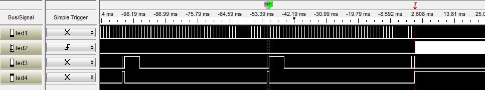
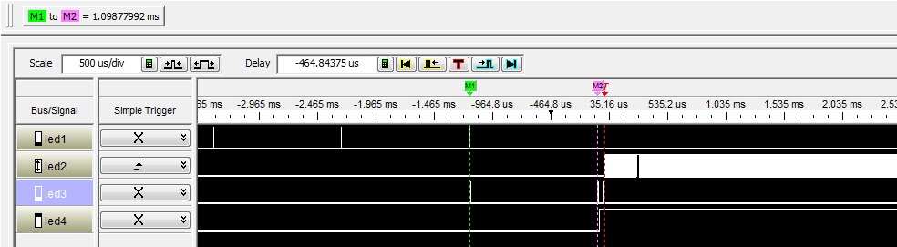
When the Task_sleep is commented out, as above, the system runs as expected - the task continuously executes, toggling LED_2. The timer interrupt happens every 1.67ms and pulses LED_3. See the logic analyzer capture below.

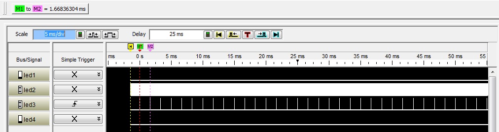
 Figure 1 - no task scheduling. The one and only task is constantly ready and executes as LED_2 shows The timer interrupt happens every 1.67ms as can be seen by observing LED_3.

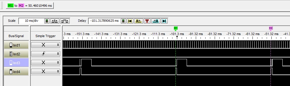
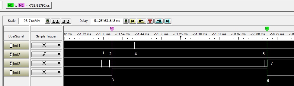
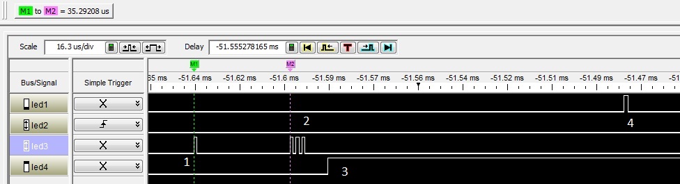
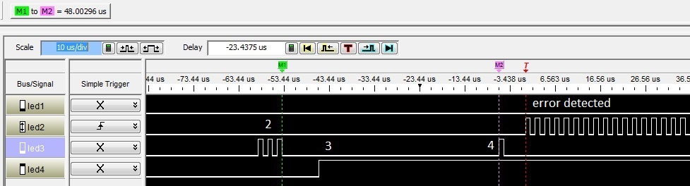
But the moment the Task_sleep is uncommented, the system starts working unexpectedly. The logic analyzer capture below shows the start of the program on the dev board.  For a few first milliseconds you can see the timer interrupts every 1.67ms and then they stop. From that moment on, the timer interrupt would still happen, albeit sporadically. See figure 3.  Strangely enough, the subsequent timer interrupts would always coincide with the time when the task wakes up.

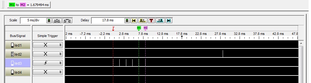
Figure 2. - starting the application with RTOS switching.  The timer ISR runs for a short while but then breaks.

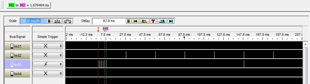
Figure 3 - the same trace as in figure 2, but zoomed out.

We suspect that there is a problem with TI-RTOS and would like to hear a comment from TI people.

Thank you,

Sergey

  • Hi,

    thank you very much for this excellent and detailed report.

    Three comments:

    1) The problem is that TI-RTOS does not know that standby is not allowed while the timer is running. Task_sleep() let the kernel enter standby mode because it assumes that nothing has to be done. Power_setDependency() just guarantees that the related power domain is switched on. It does not prevent the system from going to standby. What you need here, is an additional constraint Power_setConstraint(PowerCC26XX_SB_DISALLOW) in order to prevent from standby.

    2) A cleaner way of setting up a custom hardware interrupt handler is provided by the Hwi module in TI-RTOS. Here is an application source file where the interrupt is set up using Hwi and works as expected:

    #include <stdlib.h>
    #include <xdc/std.h>
    #include <xdc/runtime/System.h>
    
    #include <ti/sysbios/BIOS.h>
    #include <ti/sysbios/knl/Task.h>
    #include <ti/sysbios/knl/Mailbox.h>
    #include <ti/sysbios/knl/Event.h>
    
    /* Drivers */
    #include <ti/drivers/rf/RF.h>
    #include <ti/drivers/PIN.h>
    #include <driverlib/timer.h>
    #include <ti/drivers/Power.h>
    #include <ti/drivers/power/PowerCC26XX.h>
    
    /* Board Header files */
    #include "Board.h"
    
    
    PIN_Handle ledPinHandle;
    PIN_State ledPinState;
    
    
    #define TASK_STACK_SIZE 1024
    #define TASK_PRIORITY   2
    
    Hwi_Struct timerHwi;
    
    void waitingTaskFunction(UArg arg0, UArg arg1);
    
    static Task_Params waitingTaskParams;
    Task_Struct waitingTask;
    static uint8_t waitingTaskStack[TASK_STACK_SIZE];
    
    void interruptTimerA(UArg arg0)
    {
      uint32_t status = TimerIntStatus(GPT0_BASE, true);
      PIN_setOutputValue(ledPinHandle, Board_LED3,1);
    
      if (TIMER_TIMA_TIMEOUT & status) {
        TimerIntClear(GPT0_BASE, TIMER_TIMA_TIMEOUT);
      }
    
      PIN_setOutputValue(ledPinHandle, Board_LED3,0);
    }
    
    void timerInit(void)
    {
      /* Switches the peripheral power domain on */
      Power_setDependency(PowerCC26XX_PERIPH_GPT0);
    
      /* Prevents the controller from going to standby */
      Power_setConstraint(PowerCC26XX_SB_DISALLOW);
    
      // register ISR and enable hardware interrupt for timer
      Hwi_Params params;
      Hwi_Params_init(&params);
      params.enableInt = TRUE;
      Hwi_construct(&timerHwi, INT_GPT0A, &interruptTimerA, &params, NULL);
    
      /* Configure the timer hardware */
      TimerDisable(GPT0_BASE, TIMER_A);
      TimerConfigure(GPT0_BASE, TIMER_CFG_SPLIT_PAIR | TIMER_CFG_A_PERIODIC | TIMER_CFG_B_PERIODIC);
      TimerPrescaleSet(GPT0_BASE, TIMER_A, 255); // prescaler is 256 - 187.5 kHz
    
      TimerLoadSet(GPT0_BASE, TIMER_A, 313); // a random number
    
      TimerIntClear(GPT0_BASE, TIMER_TIMA_TIMEOUT);
      TimerIntEnable(GPT0_BASE, TIMER_TIMA_TIMEOUT);
      TimerEnable(GPT0_BASE, TIMER_A);
    }
    
    
    void WaitingTask_init(void)
    {
      Task_Params_init(&waitingTaskParams);
      waitingTaskParams.stackSize = TASK_STACK_SIZE;
      waitingTaskParams.priority = TASK_PRIORITY;
      waitingTaskParams.stack = &waitingTaskStack;
      Task_construct(&waitingTask, waitingTaskFunction, &waitingTaskParams, NULL);
    }
    
    void waitingTaskFunction(UArg arg0, UArg arg1)
    {
      timerInit();
    
      for (;;) {
        Task_sleep(30 *1000 / Clock_tickPeriod);               // 30 ms wait
        PIN_setOutputValue(ledPinHandle, Board_LED2, 1);
        PIN_setOutputValue(ledPinHandle, Board_LED2, 0);
      }
    }
    
    
    int main(void)
    {
      Board_initGeneral();
    
      ledPinHandle = PIN_open(&ledPinState, BoardGpioInitTable);
      if (!ledPinHandle) {
        System_abort("Error initializing board LED pins\n");
      }
    
      WaitingTask_init();
      BIOS_start();
      return (0);
    }
    

    3) TI-RTOS task and hwi setup needs a lot of boiler plate code. A more convenient and less error-prone way is, to use XDC's code generation facilities. This is explained in chapter 3 of this document. The additional lines in your .cfg file would be:

    /* ================ Application Specific Instances ================ */
    var m3Hwi0Params = new m3Hwi.Params();
    m3Hwi0Params.instance.name = "timerHwi";
    Program.global.timerHwi = m3Hwi.create(31, "&interruptTimerA", m3Hwi0Params);
    var task0Params = new Task.Params();
    task0Params.instance.name = "waitingTask";
    task0Params.stackSize = 1024;
    Program.global.waitingTask = Task.create("&waitingTaskFunction", task0Params);

    And your main source file would become:

    #include <stdlib.h>
    #include <xdc/std.h>
    #include <xdc/runtime/System.h>
    
    #include <ti/sysbios/BIOS.h>
    #include <ti/sysbios/knl/Task.h>
    
    /* Drivers */
    #include <ti/drivers/PIN.h>
    #include <driverlib/timer.h>
    #include <ti/drivers/power/PowerCC26XX.h>
    
    /* Board Header files */
    #include "Board.h"
    
    PIN_Handle ledPinHandle;
    PIN_State ledPinState;
    
    /* Hwi is created from the .cfg file */
    void interruptTimerA(UArg arg0)
    {
      uint32_t status = TimerIntStatus(GPT0_BASE, true);
      PIN_setOutputValue(ledPinHandle, Board_LED3,1);
    
      if (TIMER_TIMA_TIMEOUT & status) {
        TimerIntClear(GPT0_BASE, TIMER_TIMA_TIMEOUT);
      }
    
      PIN_setOutputValue(ledPinHandle, Board_LED3,0);
    }
    
    
    void timerInit(void)
    {
      /* Switches the peripheral power domain on */
      Power_setDependency(PowerCC26XX_PERIPH_GPT0);
    
      /* Prevents the controller from going to standby */
      Power_setConstraint(PowerCC26XX_SB_DISALLOW);
    
      /* Configure the timer hardware */
      TimerDisable(GPT0_BASE, TIMER_A);
      TimerConfigure(GPT0_BASE, TIMER_CFG_SPLIT_PAIR | TIMER_CFG_A_PERIODIC | TIMER_CFG_B_PERIODIC);
      TimerPrescaleSet(GPT0_BASE, TIMER_A, 255); // prescaler is 256 - 187.5 kHz
    
      TimerLoadSet(GPT0_BASE, TIMER_A, 313); // a random number
    
      TimerIntClear(GPT0_BASE, TIMER_TIMA_TIMEOUT);
      TimerIntEnable(GPT0_BASE, TIMER_TIMA_TIMEOUT);
      TimerEnable(GPT0_BASE, TIMER_A);
    }
    
    /* Task is created from the .cfg file */
    void waitingTaskFunction(UArg arg0, UArg arg1)
    {
      timerInit();
    
      for (;;) {
        Task_sleep(30 *1000 / Clock_tickPeriod);               // 30 ms wait
        PIN_setOutputValue(ledPinHandle, Board_LED2, 1);
        PIN_setOutputValue(ledPinHandle, Board_LED2, 0);
      }
    }
    
    
    int main(void)
    {
      Board_initGeneral();
    
      ledPinHandle = PIN_open(&ledPinState, BoardGpioInitTable);
      if (!ledPinHandle) {
        System_abort("Error initializing board LED pins\n");
      }
    
      BIOS_start();
      return (0);
    }
    

    Best regards

    Richard

  • Richard, all your three comments are noted and much appreciated.  Yes, the code now works as expected.

    Thank you very much,

    Sergey

  • Hi Richard,

    even though the test code above started working fine, we are still experiencing issues with our actual project and even after we disabled the standby as you suggested.   It is possible that while trying to build a test case for you, I didn't really replicate all of the issues that caused our system to fail.    

    My attempts to built another test project to demonstrate the failure that we see in our system didn't succeed. I hope that if I give you a verbal description you might be able to at least point me to where I should start looking more closely for an explanation.

     So, as in the code above, we have a heartbeat task that sleeps for a period of time( in this case it is exactly 1.098 ms), increments a counter and goes back to sleep.  It also blinks an LED when the task wakes up.

     Another task is waiting for an event that is posted by the timer ISR.   There are actually two interrupts generated by the GPTM - the match interrupt and the timeout interrupt.  They are about 750us apart, with a period of say 50ms.  I am not sure if it is relevant.

    Each of these two interrupts posts its own event to the waiting task.

     On the first event the waiting task wakes up, does something (prepares data for transmission in our system) and starts waiting for the second event . Upon waking up on the second event it starts transmission, finishes it and goes for the wait for the first event again.

    It is a periodic process that happens every 50ms and I have LEDs that mark every event in this system.

     Here is the logic analyzer capture for it.


    In this capture, the LED1 - is when the heartbeat task wakes from sleep, every 1.098ms.

    LED3 shows interrupt activity and timing of the waiting task, as will be explained later.

    LED4 is the time when the waiting task is pending on the second event - start of transmission, as explained later.

    The capture below is a zoomed in fragment of activity.


    The LED 3 captures interaction between timer ISR and the waiting task.  Will be explained in the expanded view later.

    LED4 is about 750 ms  - time the waiting task pends on the second event from the timer interrupt. Shown here for clarity only.


    This capture shows the complete interaction between ISRs and the waiting task. The time point labeled 1 is where the timer ISR happens, just before it sends the first event to the waiting task.  Time point 2 (actually comprised of three quick pulses of the LED3) is when the waiting task wakes up on the event and starts pending on the second event at time point 3 of the LED4.  There is about 30 usec switching time, which is about normal.

    Note the time point 4 - it is where the heartbeat task wakes up from its periodic sleep.  Because sys timer of the RTOS is not synchronized to the GPTM , the location of the heartbeat task wake up constantly changes relative to the waiting task activity.

     The time point 5 is when the second interrupt happens in the timer, posts an event to the waiting task which wakes up the waiting task at point 6 where the transmission starts at point 7.

    The capture below shows the detailed fragment of events 1-4.


    1 - Timer interrupt before it posts the first event. 2 - the waiting task woke up, 3 - the task started pending on the second event. 4 - the heartbeat task woke up and went back to sleep.


    This sequence breaks after a random time, minutes or hours. Below is what happens at that time.


    In this capture the error condition is detected, as indicated on LED2.  The capture below zooms in to the area.


    This is the most important capture.  The first pulse on the LED3 is when the first timer interrupt happened.  Please note that the heartbeat task wake up coincided with it - LED1. On the capture they are a few microseconds apart, meaning that the hardware interrupt from the GPTM likely happened in exactly same time as the RTOS sys timer interrupt did. The result of it is absolutely strange.

    The first event posted by the timer ISR arrives to the waiting task EXACTLY 1.098 ms after this, as can be seen above , upper left corner, in the M1 to M2 markers distance. Not in 30 usec, but in 1.098ms.  As if time stopped for the system for the duration of the heartbeat task waiting period.  And this is a problem.

    After the 1.098 ms delay the execution continues. The capture below is the zoomed area of that time.


    Three pulses at the time point 2 are where the waiting task woke up, point 3- where it starts waiting on the second event, 4 - the timer ISR happened, which was in a totally wrong time, and the system detected it and went to error condition as LED2 showed.

    We captured the same behavior many times. Every time when the system breaks we see the system timer interrupt, that woke up the heartbeat task, coincide with the GPTM interrupt.  And every time the system "freezes" for exactly the sleeping period of the heartbeat task.  If I configure the heartbeat to sleep for 3 millisecond, the error behavior will be the same, but system will freeze for 3 ms etc.

    I call it a "freeze" because this condition disables global interrupts, or at least the GPTM interrupt,  and blocks the waiting task for  exactly the period of the heartbeat task sleeping. I can't imagine a software error on our side that could explain this "cross contamination" and RTOS behavior.  A stack overflow could cause something like this, but we checked and eliminated this cause.

    Do you have any suggestions what it might be?

    Thank you,

    Sergey


  • Hi,

    thanks again for illustrating your issue with timing diagrams. As I am currently travelling, I can not really look it into this. I suggest:

    • Please provide some code again that shows your setup and reproduces that issue.
    • Maybe move this thread into the general TI-RTOS forum or start a new one. A moderator can do that if you agree. TER?

    Richard

  • HI Richard,

    it appears that the problem is with me using

     *((u32 *)(0x20000000 + 31*4)) = (u32)interruptTimerA;

     IntEnable(31);

    to register the interrupt with NVIC  and enable it instead of using Hwi_Construct.

    You mentioned that the latter was a cleaner method, but it appears not using it creates strange artifacts when timer interrupts coincide in time with RTOS system timer interrupts.  In other words SYSBIOS APIs must be used.

    Thank you,

    Sergey

  • Hi,

    I am glad that you solved your issue. I should have been more careful with my wording in the post above. Of course the Hwi must be used to implement custom interrupt handlers. The reason is the nature of an OS. Let's assume your custom interrupt handler is executed and interrupts are still enabled. Let's now assume that another interrupt occurs and triggers a task or Swi. Because the scheduler is not aware of the custom interrupt handler, it executes the triggered task while returning from interrupt context instead of proceeding with the custom interrupt handler. This is the "strange artifacts" that you observe.

    Richard

  • How to make the system can turn into standby when not in use when the timer? is it use Power_releaseConstraint(PowerCC26XX_SB_DISALLOW)?
  • Please refer to the power management guide. The functions

    Power_setDependency(PowerCC26XX_PERIPH_XXX);
    Power_releaseDependency(PowerCC26XX_PERIPH_XXX);

    control whether the peripheral domain is switched on or off when the main CPU is in running state while the antigonists

    Power_setConstraint(PowerCC26XX_SB_DISALLOW);
    Power_releaseConstraint(PowerCC26XX_SB_DISALLOW);

    control whether the CPU is allowed to go into standby. I will make an internal note to improve the power driver API documentation.

  • i use Power_releaseConstraint(PowerCC26XX_SB_DISALLOW),but find does not reduce the power consumption.
    THIS is my code?
    Void heartBeatFxn(UArg arg0, UArg arg1)
    {
    while (1) {


    Semaphore_pend( Mcp2023aSemSemHandle, BIOS_WAIT_FOREVER);

    Power_releaseConstraint(PowerCC26XX_SB_DISALLOW);
    }
    }
    void TimerIsr0(UArg arg)
    {
    // Task_sleep(5000);
    TSTermDevId IdentDevId;
    TimerIntClear(GPT0_BASE, TIMER_TIMA_TIMEOUT);

    if(Mcp2030a_Data.Mcp2030a_RecvDataCount < (Mcp2030a_RecvBit - 1)) //接收23位数据
    {
    Mcp2030a_Data.Mcp2030a_RecvBuffer <<= 1;
    Mcp2030a_Data.Mcp2030a_RecvBuffer += Mcp2030a_Lfdata_Input;

    if(Mcp2030a_Lfdata_Input)
    {
    Power_Detect_Enable;
    }
    else
    {
    Power_Detect_Disable;
    }
    if(Mcp2030a_Data.LeaveIdentRegFlag == 1)
    {
    if(Mcp2030a_Data.WakeupCount == 0xa5)
    {
    Mcp2030a_Data.WakeupCount = 0x5a;
    }
    if(Mcp2030a_Data.LeaveIdentRegionCount > 0)
    {
    Mcp2030a_Data.LeaveIdentRegionCount = 0;
    }
    Mcp2030a_Data.LeaveIdentRegFlag = 0;
    }
    Mcp2030a_Data.Mcp2030a_RecvDataCount += 1;
    }

    if(Mcp2030a_Data.Mcp2030a_RecvDataCount == (Mcp2030a_RecvBit - 1)) //接收完成
    {
    TimerDisable(GPT0_BASE, TIMER_A);
    Power_releaseConstraint(PowerCC26XX_SB_DISALLOW);
    if(Mcp2030a_Data.Mcp2030a_RecvBuffer > 0)
    {
    count1++;
    Mcp2030a_Data.Mcp2030a_RecvData = Mcp2030a_Crc(Mcp2030a_Data.Mcp2030a_RecvBuffer); //CRC校验成功,则返回接收数据
    if(Mcp2030a_Data.Mcp2030a_RecvData > 0)
    {
    successcount2++;

    IdentDevId.DevNumber = (uint8_t)Mcp2030a_Data.Mcp2030a_RecvData & 0x00ff;
    IdentDevId.DevType = (uint8_t)(Mcp2030a_Data.Mcp2030a_RecvData >>= 8) & 0x0ff;

    switch(IdentDevId.DevType)
    {
    case Dev_Pollute_Recog: //污染区识别器
    case Dev_Aseptic_Recog: //无菌区识别器
    case Dev_Washing_Field_Recog: //水洗区识别器
    case Dev_FastWash_Bottle_Recog: //速消区液瓶识别器
    case Dev_WaterWash_Bottle_Recog: //水洗区液瓶识别器
    case Dev_Outside_Door_Recog: //门外识别器
    case Dev_Inside_Door_Recog: //门内识别器
    if(IdentDevId.DevNumber > 0)
    {
    if(Mcp2030a_Data.Mcp2030a_RecvIfg == false)
    {
    Mcp2030a_Data.IdentDevId[0].DevType = IdentDevId.DevType;
    Mcp2030a_Data.IdentDevId[0].DevNumber = IdentDevId.DevNumber;

    Mcp2030a_Data.Mcp2030a_RecvIfg = true;
    Mcp2030a_Data.DataProc_Over = false;
    }
    }
    break;
    case Dev_Sickbad_Recog: //病床区识别器
    if(Mcp2030a_Data.Mcp2030a_RecvCount < 3) //接收3次
    {
    Mcp2030a_Data.IdentDevId[Mcp2030a_Data.Mcp2030a_RecvCount].DevType = IdentDevId.DevType;
    Mcp2030a_Data.IdentDevId[Mcp2030a_Data.Mcp2030a_RecvCount].DevNumber = IdentDevId.DevNumber;
    Mcp2030a_Data.Mcp2030a_RecvCount += 1;
    }

    if(Mcp2030a_Data.Mcp2030a_RecvCount == 3)
    {
    if((Mcp2030a_Data.IdentDevId[0].DevNumber == Mcp2030a_Data.IdentDevId[1].DevNumber)
    && (Mcp2030a_Data.IdentDevId[0].DevNumber == Mcp2030a_Data.IdentDevId[2].DevNumber))
    { //如果3次相等,则识别完成
    if(Mcp2030a_Data.Mcp2030a_RecvIfg == false)
    {
    Mcp2030a_Data.Mcp2030a_RecvIfg = true;
    }
    }
    Mcp2030a_Data.Mcp2030a_RecvCount = 0;
    }

    if(Mcp2030a_Data.Mcp2030a_RecvCount > 3)
    {
    Mcp2030a_Data.Mcp2030a_RecvCount = 0;
    Mcp2030a_Data.Mcp2030a_RecvBuffer = 0;
    Mcp2030a_Data.Mcp2030a_RecvIfg = false;
    memset((uint8_t *)&Mcp2030a_Data.IdentDevId[0],0,sizeof(TSTermDevId));
    memset((uint8_t *)&Mcp2030a_Data.IdentDevId[1],0,sizeof(TSTermDevId));
    memset((uint8_t *)&Mcp2030a_Data.IdentDevId[2],0,sizeof(TSTermDevId));
    }
    break;
    default:
    Mcp2030a_Data.Mcp2030a_RecvBuffer = 0;
    Mcp2030a_Data.Mcp2030a_RecvIfg = false;
    Mcp2030a_Data.Mcp2030a_RecvCount = 0;
    Mcp2030a_Data.DataProc_Over = false;
    memset((uint8_t *)&Mcp2030a_Data.IdentDevId[0],0,sizeof(TSTermDevId));
    memset((uint8_t *)&Mcp2030a_Data.IdentDevId[1],0,sizeof(TSTermDevId));
    memset((uint8_t *)&Mcp2030a_Data.IdentDevId[2],0,sizeof(TSTermDevId));
    break;

    }
    Semaphore_post( Mcp2023aSemSemHandle);


    }


    }

    Mcp2030a_Data.Mcp2030a_RecvDataCount = 0;
    Mcp2030a_Data.DataProc_Over = false;

    }
    }


    void intCallbackFxn(PIN_Handle handle, PIN_Id pinId) {


    if (PIN_getInputValue(pinId)) {

    switch (pinId) {
    case Mcp2030a_Lfdata:

    if(Mcp2030a_Data.DataProc_Over == false)
    {
    Mcp2030a_Data.DataProc_Over = true;
    Mcp2030a_Data.Mcp2030a_RecvBuffer = 0;
    Mcp2030a_Data.Mcp2030a_RecvBuffer += Mcp2030a_Lfdata_Input; //开始接收设备ID
    if(Mcp2030a_Lfdata_Input)
    {
    Power_Detect_Enable;
    }
    else
    {
    Power_Detect_Disable;
    }

    Power_setConstraint(PowerCC26XX_SB_DISALLOW);
    TimerEnable(GPT0_BASE, TIMER_A);
    }

    break;


    default:
    /* Do nothing */
    break;
    }
    }
    }
    /*
    * ======== main ========
    */
    int main(void)
    {
    Task_Params taskParams;
    Semaphore_Params semParam;
    Board_initGeneral();
    /* Construct heartBeat Task thread */
    Task_Params_init(&taskParams);
    taskParams.stackSize = TASKSTACKSIZE;
    taskParams.priority = 2;
    taskParams.stack = &task0Stack;
    Task_construct(&task0Struct, heartBeatFxn, &taskParams, NULL);

    Semaphore_Params_init(&semParam);
    Semaphore_construct(&Mcp2023aSem, 0, &semParam);
    Mcp2023aSemSemHandle = Semaphore_handle(&Mcp2023aSem);
    /* Open LED pins */
    ledPinHandle = PIN_open(&ledPinState, ledPinTable);
    if(!ledPinHandle) {
    System_abort("Error initializing board LED pins\n");
    }
    McpPinHandle=PIN_open(&McpPinState, McpPinTable);
    if(!McpPinHandle) {
    System_abort("Error initializing Mcp2030a pins\n");
    }
    Timer_init();
    Mcp2030a_Init(); //初始化mcp2030a
    /* Setup callback for button pins */
    if (PIN_registerIntCb(McpPinHandle, &intCallbackFxn) != 0) {
    System_abort("Error registering Int callback function");
    }

    PIN_setOutputValue(ledPinHandle, Board_LED1, 1);
    PIN_setOutputValue(ledPinHandle, Board_LED0, 1);

    BIOS_start();

    return (0);
    }

    ////////////* 使用定时器0产生200uS中断 *////////////
    void Timer_init(void)
    {
    Hwi_Params hwiParams;
    Power_setDependency(PowerCC26XX_PERIPH_GPT0);

    TimerDisable(GPT0_BASE, TIMER_A);
    TimerConfigure(GPT0_BASE, TIMER_CFG_SPLIT_PAIR | TIMER_CFG_A_PERIODIC_UP);
    Hwi_Params_init(&hwiParams);
    hwiParams.enableInt=1;
    Hwi_construct(&TimerHwi, INT_GPT0A, TimerIsr0,&hwiParams, NULL); //注册中断服务函数
    // TimerStallControl(GPT0_BASE, TIMER_A, 1);
    TimerLoadSet(GPT0_BASE, TIMER_A, 9600);
    TimerPrescaleSet(GPT0_BASE, TIMER_A, 0);
    // TimerPrescaleMatchSet(GPT0_BASE, TIMER_A, 0);
    TimerIntClear(GPT0_BASE, TIMER_TIMA_TIMEOUT);
    TimerIntEnable(GPT0_BASE, TIMER_TIMA_TIMEOUT);
    // TimerEnable(GPT0_BASE, TIMER_A);
    }
  • I would like to look into your code, but I cannot spend much time on that. Therefore please attach a full example that compiles and also reduce the complexity. If you simplify your code, maybe you already find the error by your self. That happens to me very often.

    And please proceed in the other thread that you created relating the same issue in order to keep threads related to their initial topic. 

    Thanks. Best regards.