This thread has been locked.

If you have a related question, please click the "Ask a related question" button in the top right corner. The newly created question will be automatically linked to this question.

CC1310 interoperability

Other Parts Discussed in Thread: CC1310, MSP430F5529

Hello,

I am relatively new to RF but have successfully got two CC1310s communicating using two CC1310DK kits and SmartRF studio 7. Using the same settings the example projects also worked as expected for me (rfPacketRx_CC1310DK_7XD_TI_CC1310F128 and the corresponding TX version).

Now however I've been handed a new requirement to make these devices work with a legacy system. I have two examples of the legacy devices but the actual RF chip used on it seems to be a closely guarded secret (the part is covered in epoxy and the client will not, or cannot, tell me). I'm told these legacy devices work as follows:

  • Centre frequency: 868.9MHz
  • Modulation: FSK
  • Frequency deviation: 45kHz
  • Bit rate: 20kbps
  • TX bandwidth: 400kHz
  • TX Power: 12 dBm
  • RX bandwidth: 100kHz
  • 4 byte preamble: 0x55 0x55 0x55 0x55
  • 4 byte sync: 0x1A 0x2B 0x3C 0x4D
  • Whitening enabled on one device, disabled on the other

However, when experimenting with different settings in SmartRF Studio I am unable to get the devices to communicate with the CC1310 (send or receive, with or without whitening). In continuous RX mode I can however see that the devices are transmitting when I expect them to.

I think I'm setting the device to use FSK correctly (CMD_PROP_RADIO_DIV_SETUP->modulation->modType set to 0), and the centre frequency and frequency deviation seems straight forward.

I don't fully understand how the bit rate matches up with the symbol rate in SmartRF Studio (or it's importance) so can anybody clarify?

I see how to set the sync bytes (I'm not sure of the endianness, but I've tried all options), but how do I set the preamble (is it possible to set)? I see there's a field for it in the "Packet TX" tab, but it is greyed out and not editable for me.

I hope I'm missing a small detail, but due to my lack of RF experience, and my inexperience with the CC1310, I don't know what or where to look next. I'm hoping somebody here can give me some hints on how to set up SmartRF studio to match these settings, and/or advise on a strategy to determine the required settings.

Thanks,

K

  • If you look at the low right corner: The status should be DONE_OK for all commands except for CMD_PROP_RX which should be ACTIVE. I see the status in your case is IDLE indication that you have not entered Rx. Do you always get IDLE even after restart/ power on/ off?
  • Sorry, I didn't notice that when I took the screenshot. In fact it's not something I been paying attention to in general but will do from now on.

    However, I've double checked and can confirm that I normally do get DONE_OK and ACTIVE when I try to start receiving (but I'm still not receiving any data from the legacy devices).

    Any other suggestions gratefully appreciated.

    Thanks,

    K

  • - Rx Bandwidth: You write that the legacy device has 45 kHz deviation and a datarate equal to 20 kbps. This give a signal bandwidth around 110 kHz. Given crystal inaccuracy you have to have a Rx bandwidth that is a bit larger than your signal bandwidth to ensure that you can receive the signal. (See the post at the end of e2e.ti.com/.../151112)
    - You have typed in a different datarate/ deviation in SmartRF Studio than you state the device uses?
    - To check the sync word you can set the sync word to 0x5555 and see if you receive the expected sync word in the FIFO.
  • Thanks for the reply TER.

    - When I try to follow that link I'm told "Unfortunately, the page you've requested no longer exists."

    - Sorry, I've just noticed that I entered the incorrect deviation in my original post. It should be 30kHz, as set in both screenshots. You also say I've typed in an incorrect datarate. When I type 20 into the symbol rate box it automatically changes it to 19.99803. Is this what you are referring to? Or am I misinterpreting the bit rate (in kbps) as symbol rate (in kBaud), or am I missing something else.

    - I tried this but it didn't make any difference (I'm still not seeing any data arrive).  But I also don't understand how this would work. If the CC1310 first reads the preamble coming from the other device, the next byte will be the first sync byte, and not another preamble byte. Right? In which case will the CC1310 reject the packet because the sync word is incorrect? Or  am I completely misunderstanding how the preamble and sync bytes work?

    Is there a way to put the CC1310 in a sniffer type mode, that will report all data received. I.e. preamble bytes, sync bytes and all, without processing any of them?

    Thanks,

    K

  • Sorry, it happens sometimes when I copy links that I get an extra ). Try this:
    e2e.ti.com/.../151112

    Sorry, the datarate was correct, the deviation was different. With 30 kHz deviation I would still have used slightly larger Rx bandwidth than 100 kHz.

    We don't have a sniffer mode as such. The chip uses preamble mainly to settle some internal gain loops so for on the desk tests you don't need preamble or just a short one to be able to receive. My experience is that often the information about a legacy device contains errors, that is why I would like to check if the sync word you want to use is correct.

    Set the sync word on CC1310 to 0x5555 (16 bits), fixed packet length 20 byte and see if you manage to receive something with the datarate and deviation. Increase the Rx bandwidth some in case of frequency offsets.
  • Thanks TER, that all makes sense to me now (on the sync word and preamble). I'm away from my desk for the rest of today, but I'll try again early tomorrow morning.
  • Great! I'm making progress.

    Now whenever I see that a packet is sent by the legacy device I see data in the FIFO of the CC1310, and this is when I have the sync bytes set correctly to match the legacy device (i.e. 0x1A 0x2B 0x3C 0x4D).

    I think my problem to date, or at least a major one, was that the centre frequency documented for the legacy device was incorrect; it was in fact 868.0MHz rather than the 868.9MHz I was told (only determined this when I forgot to change the default setting in the CC1310 after changing the other settings). I assume this was probably just a typo at some stage.

    Now however I have another problem. The data being sent by the legacy device is

    1F 00 00 00 9A 02 00 00 00 .....

    but the CC1310 is reading

     e0 87 b8 59 2d a3 cc 24 57 .....

    And this is consistent (I have the legacy device set to not change the packet being sent).

    Given that the sync byes are being read correctly (e.g. if I set a single sync byte of 0x1A, I see 0x2B 0x3C and 0x4D as the first 3 bytes in the FIFO) I have hope that there is some setting I'm missing. I notice the first byte of the data has all the bits inverted between the two devices. Does this give anybody any hints as to where I might want to start looking? Or any other suggestions at this point?

    Thanks for the assistance so far,

    K

  • You say the data sent by the legacy device is: "1F 00 00 00 9A 02 00 00 00 ..." but do you know if that is the data that is actually on the air? In other words is some coding/ whitening etc done on the data you put in the legacy device Tx buffer?
  • Thanks TER.

    I got side-tracked by another task on Friday, but have tested again this morning. I mentioned in my first post that I had one legacy device with whitening enabled, and one without. It seems the two devices were mislabelled.

    When I enable "PN9 Whitening" the messages I receive from the legacy device with the label "NO WHITENING" are legible, and equally when "No whitening" is selected for the CC1310 I can understand the messages from the legacy device with the label "WHITENING". So with a 50-50 chance of getting the labelling correct, whoever prepared these legacy devices for me managed to get it 100% wrong!

    So I can now send messages from the legacy device and receive them on the CC1310. My task for today is to be able to send from the CC1310 and receive on the legacy device. I'm told there is address and CRC filtering enabled on the legacy device (although I'm now treating any such info about these legacy devices as suspect until proven otherwise) so I'll have to figure out how to format the packet appropriately. Does anybody have an opinion on whether I should stick with SmartRF Studio to try to achieve this, or should I start with one of the example applications, such as "RF Packet TX" as it might allow more flexibility?

    Thanks,
    K
  • If you want to test if the legacy device uses address filtering or not and other basic packet handling things the most efficient would be to use SmartRF Studio.
  • Good progress. I can now send data from the CC1310 and receive it on the legacy device.

    However, to do so I have to disable the CRC on the CC1310 and generate it manually as the legacy device uses a different polynomial and initialization value for the CRC.

    I see in section 23.7.5.2 (page 1686) of the "CC13xx, CC22xx SimpleLink Wireless MCU Technical Reference Manual" (SWCU117F) that the CC1310 is using the polynomial x^16 + x^15 + x^2 + 1 and initialization of all 1s, but that "...other polynomials, lengths, and initializations can be obtained by parameter overrides...".

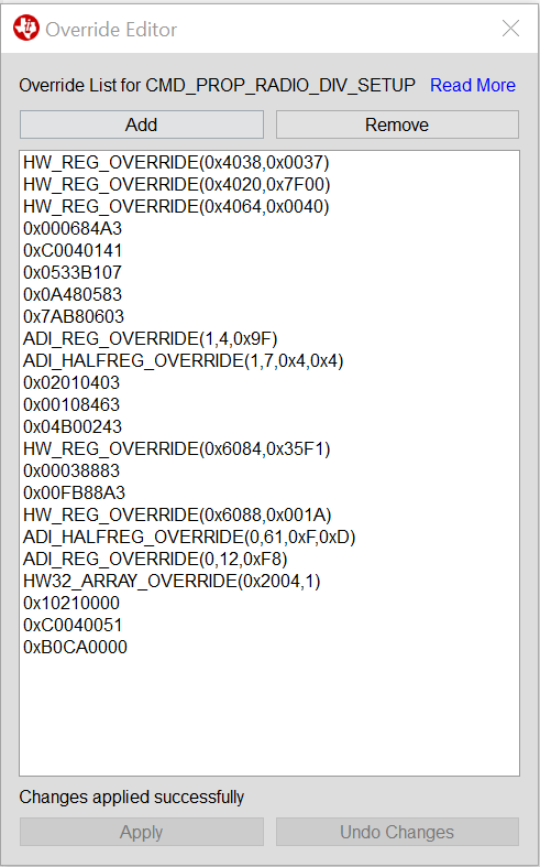
    So far I've been unable to figure out how to do this or even how the "Override Editor" in SmartRF Studio works. I must be missing some background info, because the help description of the override editor isn't making any sense to me.

    So, if, for example, I want to use a polynomial of x^16+x^12+x^5+1 and an initialisation value of 0xB0CA on the CC1310 can anybody tell me how would I go about it (in SmartRF Studio if possible)?

    Thanks,

    K

    P.s. as an aside, I still haven't figured out exactly what this legacy device is, but that CRC polynomial looked familiar, and from a quick bit of research I realise it's because I've seen it before; it's the same as the one used by the CRC module on the MSP430F5529, a part I've used extensively in the past. Does this indicate that the legacy device may be a TI part, or just that this is a standard polynomial to use for CRC?

  • The CRC looks like CRC-16-CCITT which is a common one.

    To change the CRC the following overrides should be possible to use:

    HW32_ARRAY_OVERRIDE(0x2004, 1), // configure new CRC16 poly (=0x40012005 in pure hex)
    0x10210000, // new CRC16 poly: CRC-16-CCITT normal form, 0x1021 is x^16 + x^15 + x^5 + 1
    0xC0040051, // CRC initialization (address)
    0x00000000, // CRC initialization (value)

    This looks like a nice CRC calculator: www.sunshine2k.de/.../crc_js.html
  • Thanks TER.

    I tried these settings but I'm not getting the result I expect (the CC1310 is still reporting CRC Error), but before I investigate any further, I just want to check that i'm entering the settings correctly. I've just added the 4 lines to the end of the "Override Editor". And do I have the endianess of the initialisation value (of 0xB0CA) correct?

    Thanks,

    K


  • To check if you have implemented things correctly etc:

    Use a CC1310 as Rx side and send a packet from the CC1310 you set up the CRC on. On the Rx side use fixed packet length with the length at least 2 byte more than the packet to ensure that the CRC is visible in the payload (Use SmartRF Studio) See if the CRC is the same as you would expect based on the polynom you are using.
  • Thanks TER,

    I was trying to use the CMD_PROP_RX->rxConf->bIncludeCrc setting yesterday to acieve the same thing, but it wasn't working as expected for me.

    Somebody else here has borrowed my CC1310DK for a few days, so I'll try your suggestion next week when I get it back.

    Thanks,
    K
  • Hi TER,

    I've finally retreived my CC1310DK kit, and have returned to this problem.

    After a bit more investigation I think I'm really close to a resolution. My only remaining issue is that I need to (post) invert the CRC before appending/checking on the CC1310 in order to be fully compatible with the legacy devices. Is there an override setting that you can provide to enable this?

    E.g. with the override settings you provided above I am getting a CRC of 0x80B1 from the CC1310 when sending a certain packet, but sending the same data packet from the legacy device I'm getting a CRC of 0x7F4E, which is the inverse. The documentation from the legacy device does not mention a post-inverse operation, but from what I understand this is not uncommon for CRC implementations (and I have tested a variety of other packets on both devices to confirm). 

    Thanks,

    K

  • It exist a radio parameter called crcXor which controls which value the CRC
    should be xor'ed with after the calculation.

    You can try to add the following after the other CRC overrides:

    0xC0040061, // override to set the “crcXor” setting (4-byte value)
    0xFFFFFFFF, // new “crcXor” value to use (default is 0x00000000)
  • Thanks TER, that solved my problem.

    I clicked on "Verify Answer" for your last post, but in reality it was a combination of your responses. Thanks again for all the help on this.

    K