This thread has been locked.

If you have a related question, please click the "Ask a related question" button in the top right corner. The newly created question will be automatically linked to this question.

Trouble combining GPIO, UART and ADC in CCS. Various execution errors. [launchxl-CC1350]

Other Parts Discussed in Thread: CC1350

Hello

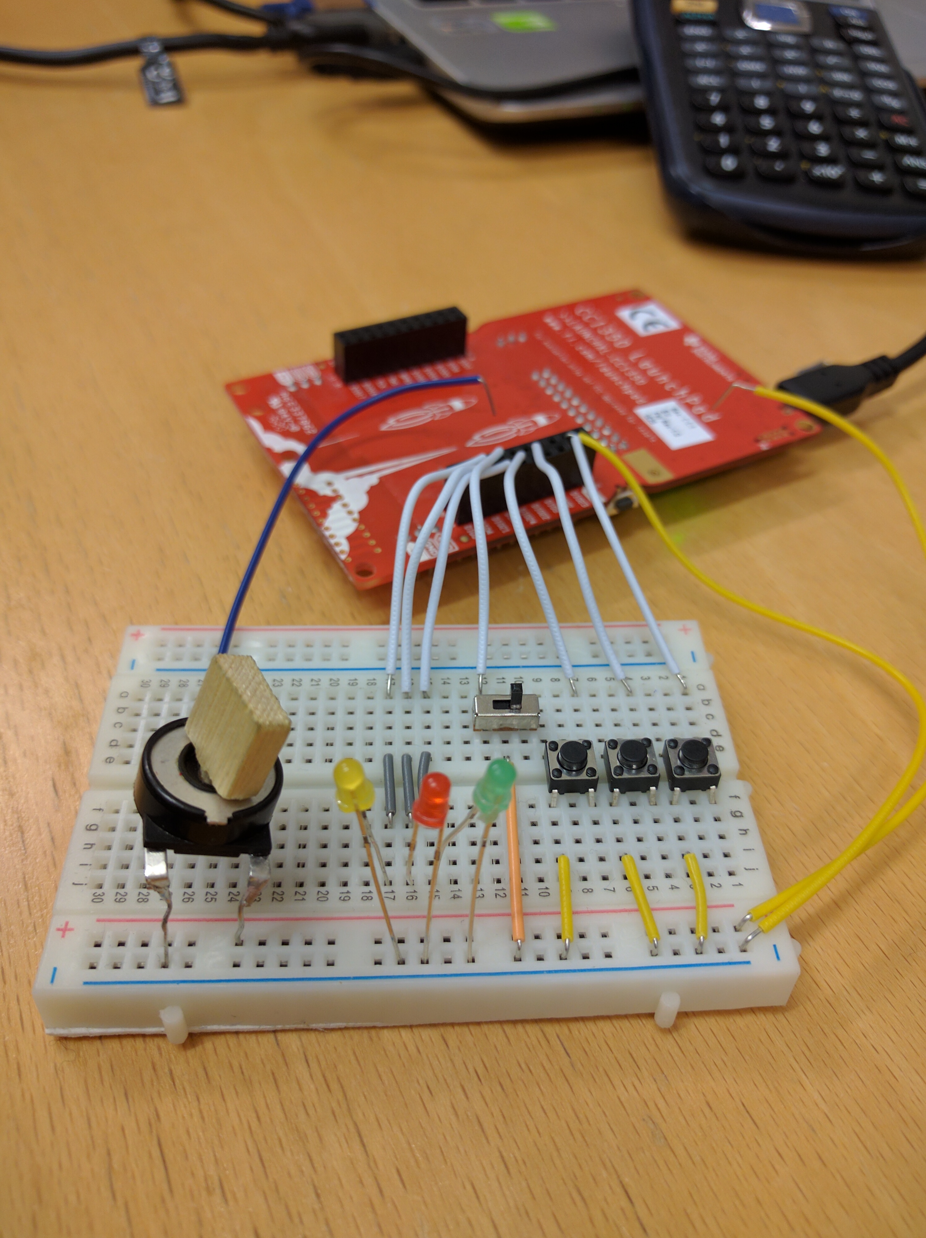
I'm working on making a CCS project that should be able to print the value on some selected GPIOs/PINs and the ADC value of a potmeter to the UART. I'm using a Breadboard with buttons, switch and potmeter as interface. I have done this by combining examples from the TI-RTOS for CC13XX and CC26XX SDK. I have made this project before, but I got quite many errors I could not understand, so I re-installed CCS. Copying the old project into the new one step-by-step, these are the problems I get.

  1. First copied moduleGPIO_zxc.c into the project and ran it from main. It worked fine. The LEDs responded as expected. Also, as default in most examples, the heartBeatFxn makes the Red LED blink with 1s interval to indicate that the system runs as normal.
  2. Then copied moduleUART_zxc.c into the project and ran it from main. Worked fine and showed the PIN-values real-time in puTTY.
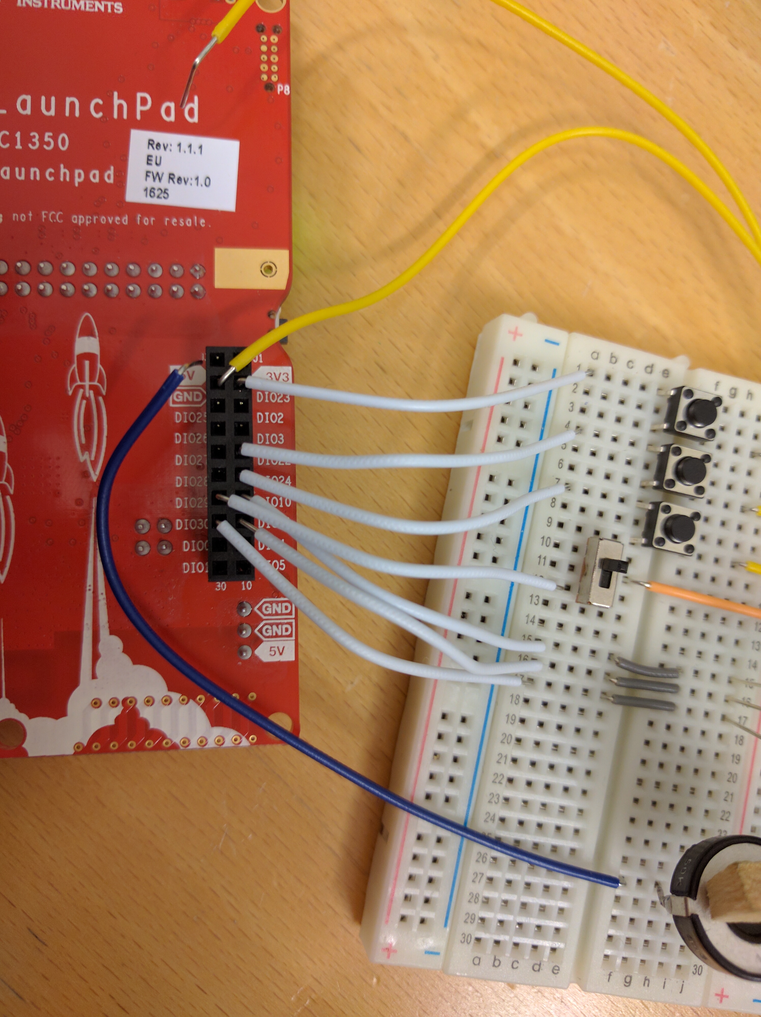
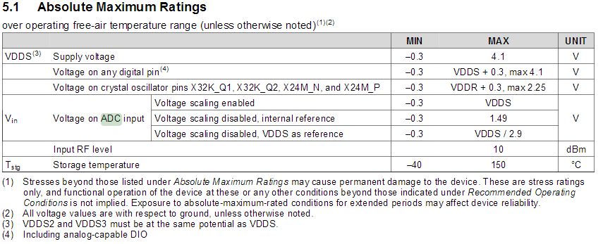
  3. Then copied moduleADC_zxc.c into the project and attached the potmeter to the Breadboard. When connecting "+"-terminal on the Breadboard to the 3V3-terminal on CC1350LP, something happened and I got the "HW ejected/HW detected" sound in Windows (the 3V3 PIN may also have touched the GND PIN).
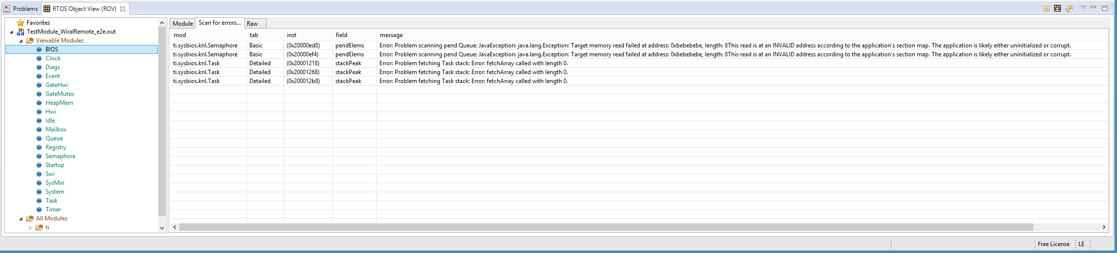
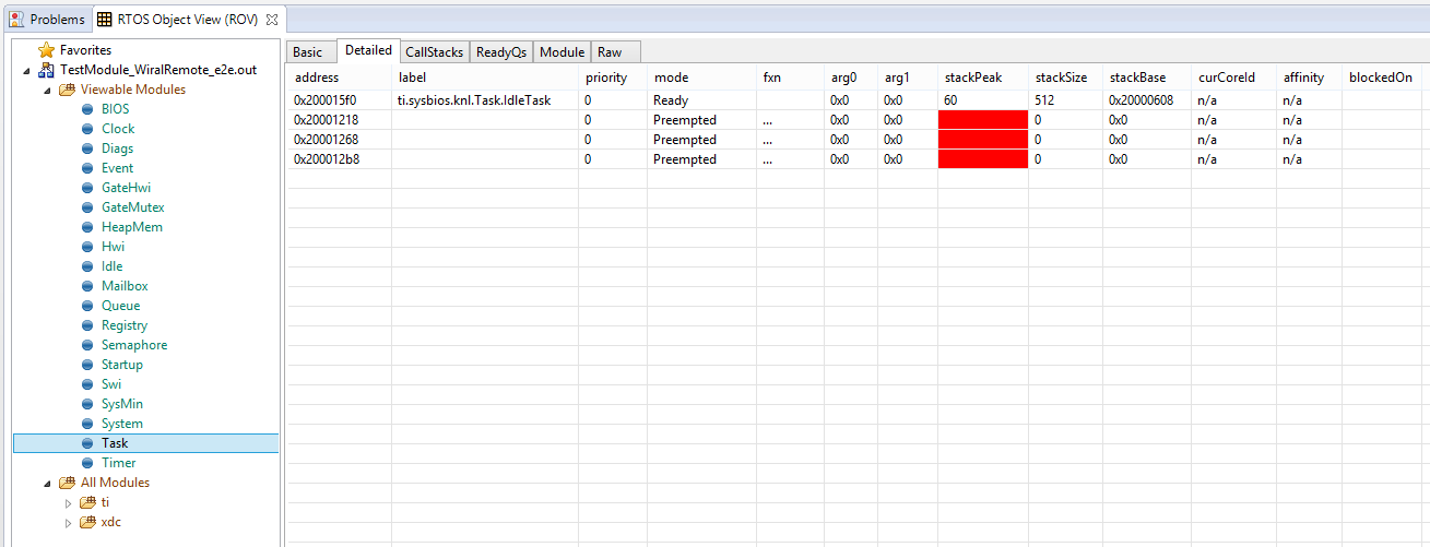
  4. Trying to run all the modules and display both PIN-values and ADC-values on the UART doesn't work. The red LED never blinks, indicating that the tasks are never executed. When trying to comment out the moduleADC_zxc.c, thus running the system as given in step 2 above, I'm still not able print anything to the UART. Only when commenting out the UART module and go back to step 1 am I able to get the system running.
  5. I've tried power cycling the CC1350LP without luck. After a few attemps I also got this error:

Cortex_M3_0: Error: (Error -1170 @ 0x0) Unable to access the DAP. Reset the device, and retry the operation. If error persists, confirm configuration, power-cycle the board, and/or try more reliable JTAG settings (e.g. lower TCLK). (Emulation package 6.0.407.6)
Cortex_M3_0: Trouble Halting Target CPU: (Error -2064 @ 0x0) Unable to read device status. Reset the device, and retry the operation. If error persists, confirm configuration, power-cycle the board, and/or try more reliable JTAG settings (e.g. lower TCLK). (Emulation package 6.0.407.6)
Cortex_M3_0: JTAG Communication Error: (Error -1170 @ 0x0) Unable to access the DAP. Reset the device, and retry the operation. If error persists, confirm configuration, power-cycle the board, and/or try more reliable JTAG settings (e.g. lower TCLK). (Emulation package 6.0.407.6)

These problems are similar to what I've gotten before, and they stop me from implementing this functionality into a radio, which is my ultimate goal. I'm therefore very interested in getting feedback to my problems. Attached is my CCS project, and pictures of my Breadboard setup. Note that the "_zxc" naming is just for customization and has no other significance.

TestModule_WiralRemote.zip

  • Hi,

    1. Can you run your application when the ADC code is implemented but disconnected?
    2. When the ADC input pin is not connected?
    3. Which reference are you using in the example (I haven't checked your source files)? If you are not using voltage scaling and the internal reference, the max voltage applied to the ADC input should not exceed 1.49V as shown in the table below (taken from the datasheet).

    I hope this helps otherwise, somebody with more experience will have to look into this.

    Regards,

    Michel

  • Hi Michael

    Thanks for the reply.

    The basic architechture of my program is that I call a "startTaskX()" from main, which lies in a separate "moduleX.c" folder, linked by a header file. The startTaskX() constructs a task of the specific module. So to answer your question.

    1. Yes and no. Just after linking the GPIO, ADC, and UART together, I was not able to get the system running again even after commenting and disabling the ADC module.  Now a while later, for unknown reasons, I am able to run the GPIO and UART with the ADC module disabled.
    2. I have been able to ran the ADC module it before. I checked now and ran it a few consequetive times in CCS, and believe this
      1. First time, NO WORK (i.e. LED is NOT blinking)
      2. Second time, WORK (i.e. LED is blinking indicating that the system are running as it should)
      3. Third time, NO WORK
      4. Fourth time, NO WORK
      5. Fifith time, WORK
      6. Sixth time, NO WORK
      7. Seventh time, WORK
      8. Eight and ninth time, WORK

    No edits between the system run above. I believe there is something deeply unstable about my code, allthough it should just be cut-and-edits from the example codes. I would therefore greatly appriciate if someone knowledgable could review my code to see if I have made some grave TI-RTOS architecture errors. General feedback on my code would also be appriciated.

    I used the ADCBuf example from TI-RTOS for CC13XX and CC26XX -v2.20 for the ADC module. 

  • Hi Birger,

    I have a CC1350 Lauchpad so I will be able to test your code from my side, however, I will not have time to do so until much later today or even tomorrow.
    In order to know what to look for in the code (and speed up the process), have you looked at the ROV? (In CCS, under the Tools menu)
    The ones that I am interested in are:
    BIOS-> Scan for errors
    Task->Module
    Task->Detailed
    Can you post some screenshots so I can see what is going?

    Regards,
    Michel
  • Thanks for taking the time, also, sorry for late reply. Now when I run it, I always get the error given above in red. I suspect I may have damaged the MC or the LaunchPad in some way. Here are the screenshots you ask for, (which are taken after the error is displayed on the console).

  • When were these screenshots taken? I am saying that because the stackBase is 0 for all tasks except for Idle.

    I guess I should have specified: can you take the snapshots when the program has failed and after BIOS_start() has started?

    As for the error, the fact that you have the Windows device ejected sound is never a good sign. This is probably because your potentiometer is not connected properly or draws too much current and causes the device to "power down". Continuously doing so could damage the board (which might already be the case). What kind of potentiometer are you using and how many Ohms?
    Can you attach a quick schematic of your ADC connections? On paper is fine.

    Regards,

    Michel

  • What does it mean that stackBase is 0 for all task except Idle? What did you expect?

    I cannot give you screenshots after the program has failed as the ROV shows "Target is not connected". I checked a few times and the ROV (BIOS->Scan for errors, Task->Module and Task->Detailed) did not change or update values in the time between I press "Resume" and when it crashes. The same values was also given before I pressed "Resume". It takes about 3-5 second from "Resume" till it crashes. The screenshots I gave you are therefore the only values I have. In my project now I only run the GPIO module and the UART module.

    I agree that the windows eject sound is bad news. The potmeter is 50kOhm, and I have managed to get it working both in CCS before and using Sensor Controller Studio. Both in CCS and in SCS I was able to output a maximum raw data number of about 3200 (of a maximum 12bit number of 4096). I connected the potmeter to the 3V3 PIN and the GND PIN, and connect a analog capable PIN for the readout, I now use DIO28 (Note that I lodded on legs on the potmeter to make it more usable). A picture of the potmeter and the simple circuit is given below, and a picture of the potmeter connection to the Breadboard is given in my original post above.

    I managed to run an empty project on the connected CC1350LP, and I got the LED blinking as it should. meaning the board isn't completely broken. Now, as mentioned above, the project crashes each time I run it even if the moduleADC is disabled. I suspect there may be error with how i construct and run the UART module, or maybe even how I use Tasks of the TI-RTOS.

    Any feedback is greatly appriciated

    Regards

    --

    Birger

  • Hi Birger,

    Birger said:
    What does it mean that stackBase is 0 for all task except Idle? What did you expect?

    stackBase should correspond to the location (address) of the stack in RAM. The address would be located in RAM which starts at 0x2000 0000. So 0 means that it has not been initialized (i.e. after BIOS_start() )

    Disconnect the ADC and try placing a breakpoint on the first line of each task. You should that the values in the ROV views will change.

    Birger said:
    Both in CCS and in SCS I was able to output a maximum raw data number of about 3200 (of a maximum 12bit number of 4096).

    The ADC can use a "scaled" reference of ~4.3V so the max value that you should obtain is 3.3 / 4.3 * 4096 = 3143.... But do not exceed the absolute maximum voltage shown in the table that I attached in my previous post.

    Birger said:
    Any feedback is greatly appriciated

    I will have to look at your code to get a better idea of what is going on. However, I will only have time much later today or even tomorrow.

    A possibility would have been that the potentiometer would draw too much current from your launchpad, but 50K will not draw enough current from the power supply to cause what you are seeing.

    The Windows eject sound leads me to believe that this is a hardware related issue and not necessarily a software issue. The ADC reads a value and it has a high impedance at its entrance so no current should be flowing in or out of the GPIO pin (unles something went wrong). Can you measure the voltage on each pin of you potentiometer for your own sake that everything is as you expect. I would also connect your potentiometer to a breadboard with an external supply just to make sure that it is not damaged (i.e. your voltage on the common changes as you turn the dial on the potentiometer)

    Let me know if you have any updates in the meantime.

    Regards,

    Michel

  • Hei Michel

    Update: I managed to remove the error and get the system working by examining the ROV with breakpoint as you said. The problem seems to be that the UART task was given the highest priority, and giving this task the lowest priorty fixed the problem.

    Now this of course brings up many new challenges for me as I have to learn tasks in detail (I couldn't get the LEDs blinking no matter the priorty I gave this task), but this is still progress. I thank you very much for your help and will mark your last reply as a verified answer. I would still appriciate it if you could give me some feedback on my code architecture, but I understand if you don't have time or feel that this is my own responsibility to understand. Thanks very much for your dedicated help.
  • Glad you got something working.

    I will still take a look because I find it strange that your board would hang if the priority is higher than your other tasks. I presume that you didn't used blocking statements for synchronization.

    I'll give you an update as soon as I take a look at your code.

    Regards
    Michel
  • I've looked at your code and there are quite few things that you could improve. I don't have time to explain everything but I'll tell you what I saw and I'll do my best to refer to proper documentation or at least give you a proper lead to where you can find the answers.

    The first thing is that you manage everything with tasks and Task_sleep for delays. That is unnecessarily hard to manage especially with different priorities.

    What you can do to improve your design:

    1. Use clocks for periodic events (Heartbeat fxn). Look at TI-RTOS clock examples to see how to use them. This will avoid using a task for a simple task and it will have a higher priority than tasks because it will run in a Swi or Hwi. In the heartbeat clock callback, do not insert any blocking calls (ex: Task_sleep, pending on modules
    2. Use interrupts for your gpio handling. Look at gpio_shutdown example If you want to react to a gpio event (it implements debouncing in a very clean way). The basic idea is that you register your interrupt function and when a GPIO change is detected, you function gets called. Again: no blocking calls in your callback function. If you need to perform long calculations or pause, you can use your task to wait for an event or semaphore. In your interrupt callback function, you would post an event or semaphore. This way, your task doesn't use a lot resources waking up all the time. You only wake your task when you have an actual event.
    3. That leaves only two other tasks: UART and ADC
    4. You should use callback mode for UART and only read one character at a time to avoid waiting for a long time for your buffer to fill. I recommend that you look at the TI-RTOS documentation for further information. On your computer, you should have a folder like this (if you installed TI-RTOS in its default location):

      C:\ti\tirtos_cc13xx_cc26xx_2_20_00_06\docs (the tirtos version might also change depending on what is installed)

      Open the Docs overview html file and click on the TI-RTOS Drivers Runtime APIs (doxygen) link. In there, you will have links to all the drivers available. I suggest that you look through the UART.h and UARTCC26XX.h links for examples of how to use callback mode

    I also discovered a problem in your code:your mailbox buffers: Mailboxes create a copy of the data that you are passing, but they also need to store additional data. You didn't include the space for the mailbox overhead. So when you create your array, you should take into consideration the size of that overhead. To make it is easier to understand: A = size of each "message"; B = size of the overhead for each "message"; C = number of messages that you can store. Here is the formula:

    Total buffer size = (A + B) x C

    The next suggestion is more for style. Avoid using extern variables. I'll give you an example of what I would do with mailboxes.
    I keep all functions related to a mailbox in a single file. Ex: one file where I use the UART mailbox, another file for ADC mailbox results. If I need to post to a mailbox, I will create a function that other files can access. So for UART, I would have my task that would Mailbox_pend for messages. I would provide a function (ex: uart_push_data(...) ) that adc could use to send messages to the UART task. I find this is a cleaner way of doing things.

    Last thing: I would recommend that you go through the Training modules available on the TI-RTOS forum:

    It will probably help you understand everything that is available to use for your design.

    Regards,

    Michel

  • This is invaluable feedback. I will implement all your improvement suggestions. I will also test you design style for mailboxes, though I have my own personal preferences.

    Were you able to run my project or did you get the same error as I did? If you only read the code, and never built it then no need, the project will be discarded anyway.

    As for the training, I tried out the 2-day workshop, but it seems I have to pay to get the software needed for the labs at the end of each chapter, I will still check this out. the videos are helpful anyway.
  • Hi Birger,
    Sorry, I did not have time to run your code.

    As for the training, once you understand what is available, the best information can be obtained from the documentation overview that I mentioned in the previous post. It provides all the links to useful documentation.
    C:\ti\tirtos_cc13xx_cc26xx_2_20_00_06\docs
    The one that you could go over is the TI-RTOS Kernel User’s Guide and for specific info about each function for the modules can be found in the cdoc link (TI-RTOS Kernel Runtime APIs and Configuration) just below.
    All the module are found under this path (tree on the left side): ti->sysbios->knl
    Regards,
    Michel
  • Birger said:
    As for the training, I tried out the 2-day workshop, but it seems I have to pay to get the software needed for the labs at the end of each chapter, I will still check this out. the videos are helpful anyway.

    Birger,

    All training is available for free in the TI RTOS workshop on the lower right side:

    https://training.ti.com/ti-rtos-workshop-series-introduction?cu=7475

    Regards,
    Svend