This thread has been locked.

If you have a related question, please click the "Ask a related question" button in the top right corner. The newly created question will be automatically linked to this question.

CC1201: Communication between CC1201 and CC1101

Part Number: CC1201
Other Parts Discussed in Thread: CC1101, , CC1190, CC1200

We have been trying to get boards using CC1201  + CC1190's and CC1101's to communicate with each other for just over a month now. So far we have had no luck.

The CC1101's communicate just fine with each other. Like wise with the CC1201 + CC1190.

Both chips have their sync words configured to  Sync0 = 91 Synce1 = D3 Sync2 = 91 Sync3 = D3

Configuration for CC1101
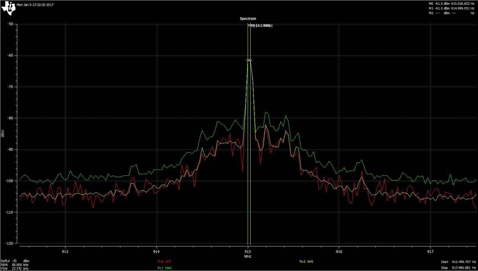
FREQ = 915MHz
Xtal FREQ = 26MHz/
Symbol Rate = 4.8ksps
RX Filter BW = 58.035714kHz
Mod Format = GFSK (have also tried 2-FSK)
Deviation 17.509Khz
TX power = 0 dBm
Manchester/PA ramping/Whitening = not enabled
Performance Mode = High
Range extender = None

Configuration for CC1201
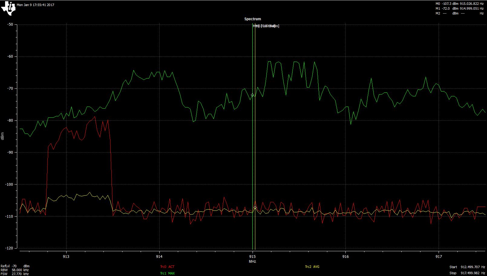
FREQ = 915MHz
Xtal FREQ = 40MHz/
Symbol Rate = 4.8ksps
RX Filter BW = 52.0833kHz
Mod Format = 2-GFSK (have also tried 2-FSK)
Deviation 17.509Khz
TX power = 26 dBm
Manchester/PA ramping/Whitening = not enabled
Performance Mode = High
Range extender = CC1190
High Gain mode(RX) = Enabled
EM Revisions = CC1200-CC1190EM 915Mhz

have tried both set to send 32 and 16 bytes of Sync word.

If anyone can send a working configuration for communication between CC1201 + CC1190 and CC1101 that would help immensely,

  • Potential issues:
    - CC1101 goes into saturation if you try to use this as receiver for the CC1201 + CC1190 signal. Make sure that when you test that the RSSI is below the saturation limit (see the RSSI curve in the CC1101 datasheet)
    - Frequency offset. The CC1101 and CC1201 based boards could have slightly different center frequency. Please verify that the boards operate at the same frequency (within about 10 kHz)
    - CC1190 control signals are set incorrectly. Not likely to be the cause since CC1201 to CC1201 based boards works.

    Please verify that the above is checked.
  • Thanks for the reply.

    I have verified the CC1101 is pretty spot on at 915Mhz, following is a screen capture of the CC1101 in continuous TX mode via RFsmart studio. The RED trace is current RF activity, GREEN is max and YELLOW is average.

    Now here are some screens from the CC1201+CC1190. We have verified the clock is indeed spot on 40Mhz. Same settings as the CC1101. But the CC1201+CC1190 seem to be channel hopping, only in MHz not KHz..

  • What type of board are you using on the CC1201 + CC1190 side? You write that you use "EM Revisions = CC1200-CC1190EM 915Mhz", to my knowledge this is a EM that doesn't exist?

    I have seen a couple of cases where the spectrum from CC1200 is too wide when the cap between pin 23 and pin 24 has used a wrong value.
  • The CC1201+CC1190 is custom. so RF studio does not talk to this board. Its just used to generate the Register values.

    Here is a pic of the EM revision in question. 

    Also the Cap between pins 23-24 is 1800pf

    .

  • - Check if you get the same Tx spectrum from the CC1201 part of the CC1201 board (remove the SAW filter and use an antenna in this point)
    - Replace C12 in case of assembly error.
    -Does the software you are running with the CC1201 + CC1190 only send a CW? Have you tried to control the board with SmartRF Studio?