This thread has been locked.

If you have a related question, please click the "Ask a related question" button in the top right corner. The newly created question will be automatically linked to this question.

CC1200: CC1200 Power transmit 5 dB loss

Part Number: CC1200


Hi. I made a custom design for 434 MHz using CC1200. I also have the CC1200-emk-420-470 kit to compare the RF performance with my design.

I started to do some tests using a microcontroller connected by spi to CC1200 for transmitting packages using texas instruments hardware and my custom board. I connect the spectrum analyzer to the SMA connector of each board and measure mean power.

My problem is that I have a -5dB difference between my board and CC1200-emk-420-470 kit using same test characteristics (messages, CC1200 configuration, VCC voltage). I follow the schematic CC120xEM 420-470MHz and used the same values for matching components, except R171: I used 20 ohms instead of 18 ohms. Can this make the difference? I don't think so.

Also I observe a little frequency shifting between designs.  Perhaps TER may help here...

I attach the power plots.
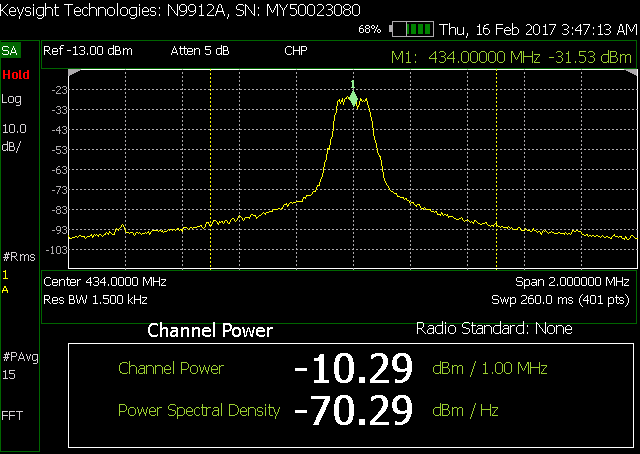
Any suggestions?

  • - Could you do the same test but sending a CW using 1 MHz RBW?
    - Could you post you schematic/ layout?
  • Hi TER. We did the same test sending a CW with 1 MHz RBW. I made a mistake in the software yesterday and now corrected it. Now I am sure that 1 dBm power is configured in both boards. Here are the plots:

    Now the frequency shift of about 19 kHz (of my custom board) is more visible and it seems to be a systematic error. I used a very similar xtal that is used in CC1200-emk-420-470 kit, so I didn't expect this shift. Perhaps texas CC1200-emk-420-470 kit is compensated in frequency from factory? Can this offset be corrected setting some register?

    The fact is that I have about -4 dB of difference between boards, but -0.56 dBm is more close to 1dBm than yesterday. What about now?

    Thanks

    SR

  • - Frequency shift:
    This could be caused by two things:
    - Use of a different xtal than we use in the ref design that requires a different Cload.
    - Different layout compared to the ref design changing the Cload. Try adjusting the load caps.

    - Output power:
    You write that you configure for 1 dBm output power but get 3 dBm, which power setting do you use?
    I need to look at the schematic/ BOM/ layout to be able to understand the output power difference. Please send me a friend request if you don't want the information open on the forum.