While trying to use the CC1125 on a custom board with the CC debugger, we're seeing logic level issues on the SPI MISO line. With our logic high as 3.3 V, we're only seeing a ~300 mV signal coming out of the MISO line and the reply itself seems incorrect based on the commands sent to the device at CC debugger powerup. (See attached photos, which show the clock pulses sent at CC debugger reset in blue, and the CC1125 reply on the MISO line in yellow)
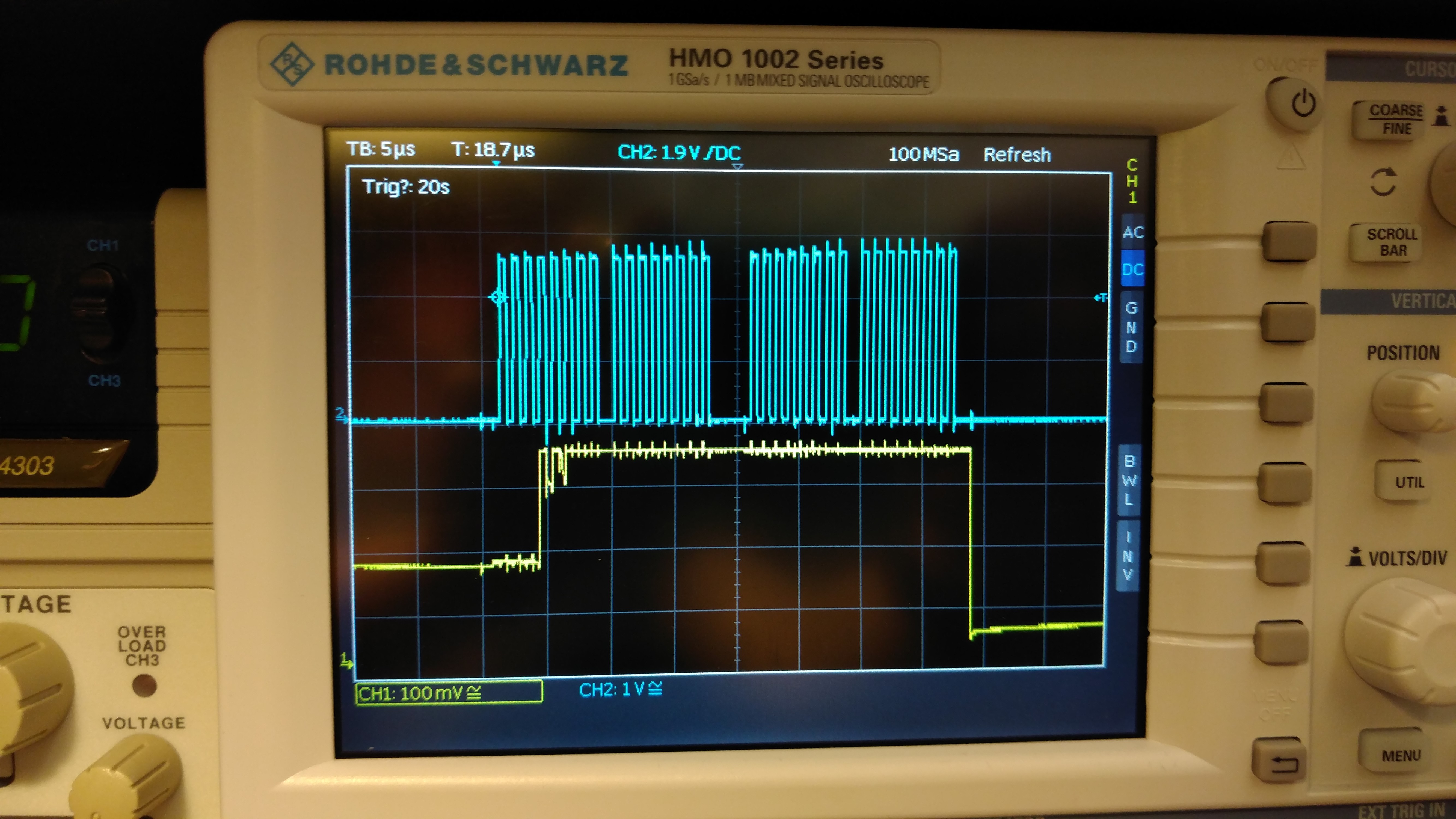

Probing our CC debugger connector on the board, we were able to decode the first commands sent to the CC1125 when the debugger is first turned on (SRES followed by SFSTXON) and subsequently verify that those lines were working as expected. However, the CC debugger LED stays red.
FYI, I've seen the following recommendations in another post, but have not yet gotten a chance to test them all. If they fix the issue, I'll just update this post and highlight those answers, but considering the behavior I'm seeing, I think it could be that the CC1125 itself is damaged.
STEPS FOR CC1125 SPI SETUP:
1. Is the xosc running? (Check pin 32)
2. Do you have 1.25 V on Rbias? (Check pin 14)
3. Do you have 1.8 V on the DCoupl pins? (Check pin 6)
4. Keep the CSn at HIGH (CSn doesn't need to be strobed, does it?)
5. Also ensure the RESET pin of CC115 must be in HIGH (CC debugger should take care of this)
6. Verify the SO is HIGH now
After all these above steps:
Pull the CSn LOW, in 18-25us you will get SO pin LOW
Thanks for any help,
Alex
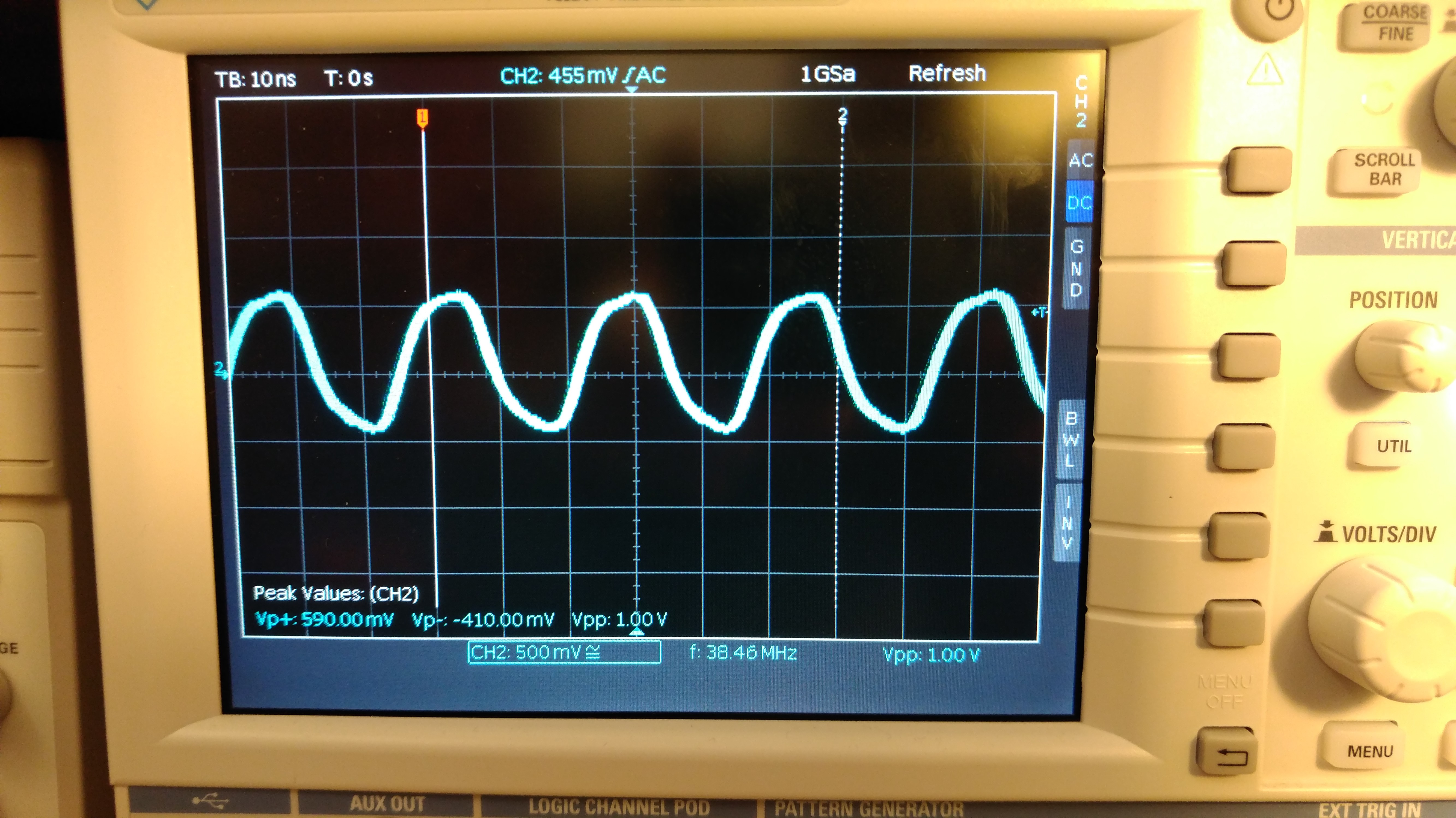
EDIT: We checked our oscillator, and the peak-to-peak voltage is too low (frequency is correct):
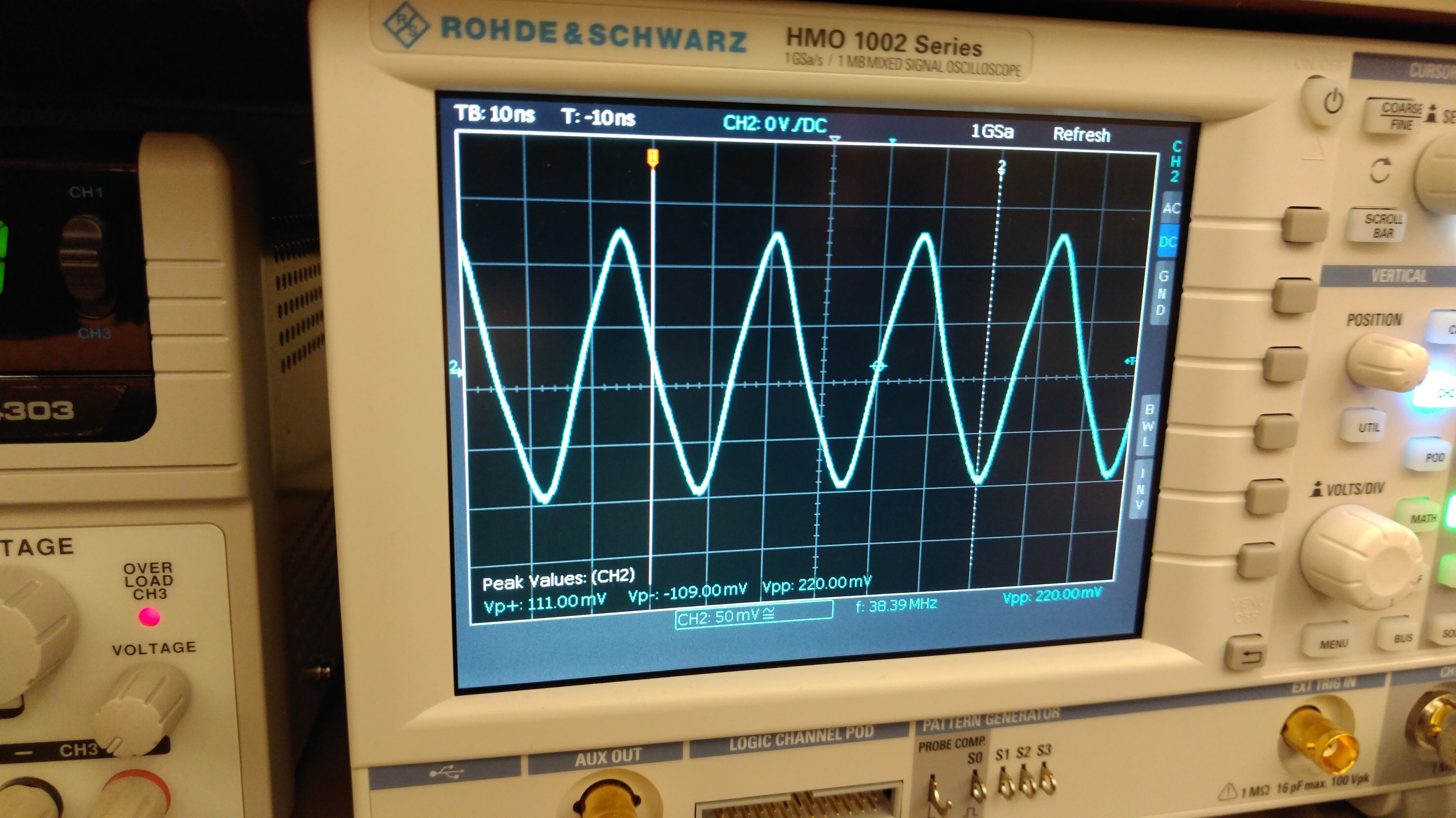
We're seeing ~0.2 mV peak-to-peak when our datasheet specifies a minimum of 0.8 V peak-to-peak when supplied with 3.3 V (supply voltage is correct).