This thread has been locked.

If you have a related question, please click the "Ask a related question" button in the top right corner. The newly created question will be automatically linked to this question.

CC1310: CC1310 - Wurth Chip Antenna - Matching Circuit

Part Number: CC1310


Hi,

I'm using the CC1310 part connected to a Wurth 7488910092 antenna.

The antenna is 868MHz, 50R.

My circuit, up to and including C2 in the image below is as per CC1310-LAUNCHXL development board.

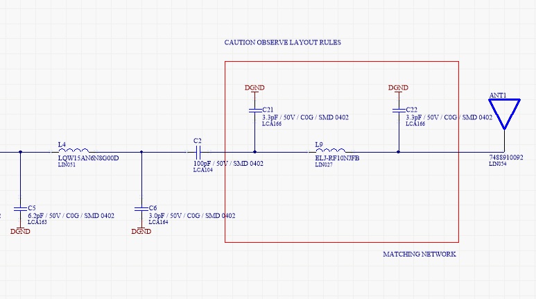
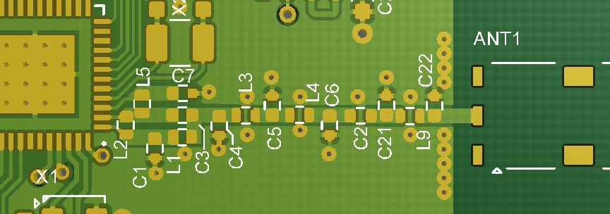
And PCB layout is as follows:

I have added the "recommended" matching network per Wurth. (its shown in the red box)

I have also tried the direct connection to the antenna, bypassing the matching network and just connect C2 directly to the antenna.

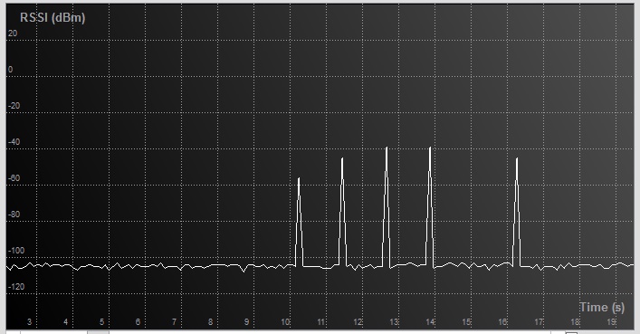
Neither solution works, in that I can't receive any data on this hardware, but I can on a LaunchXL board.  I don't have any RF tools to debug hardware.

Is anyone with experience in this area able to advise where I can look for issues? Is there maybe some SmartRF setting that I need to use to determine antenna type, etc?

Thanks.

Stomp!

  • If the RX and TX units are close you will get a link even if the antenna impedance matching on your board is not optimum. The reason why you don't get a link is most likely not linked to the matching components (although proper matching is needed to get maximum range).

    Setting up an RF link should be the very last test. If you don't, you have no way of knowing why the range is poor. In order to debug and test properly you need to do the testing in steps.

    First you need to test conducted RX and TX performance using proper lab equipment (signal generator and spectrum analyzer respectively). Disconnect the antenna and solder a semi-rigid coax cable to the antenna feedpoint. Use a good known SW for this; e.g. SmartRF Studio or CC13xx SW examples from TI web. Next you need to test the antenna separately using a network analyzer. Tune the impedance matching network if needed. When the above is done you can set up an RF link.
  • Thanks,

    Wondering if you can comment on the Antenna matching circuit. Its just a chip antenna, should be quite "plug and play". I don't have access to any test equipment unfortunately.

    Our firmware works well on CC1310 LaunchXL, but not on our boards with the chip antenna. The distance between units is only 1 meter at the moment and we are using the LaunchXL for transmission and our board with the chip antenna for reception.

    We have three possible cases:

    1. Using the matching filter as shown in the schematic above - Does not work.
    2. Using a direct connection from capacitor C2 to antenna - Does not work.
    3. Some other solution?

    Can you advise how to match the antenna or even if that matching system I've shown will even work.

    Thanks!
  • The matching network depends on the environment. The Wurth matching network is valid for the Wurth test board; not necessarily yours. For your design you might need a new set of matching components for optimum range. That said, you should get a link at 1 m distance even if the matching is not optimum so both ) and 2) above should work IF the RX path on your PCB is designed correctly and the SW is OK.

    Connect to SmartRF Studio and check the RSSI reading in the continuous RX tab. Does the reading indicate that there is a transmitter? If not, then you need to debug your PCB design and not only the antenna.

    Regarding 3). For testing you can use a different antenna approach. Instead of the Wurth antenna you can simply use a piece of copper wire as antenna. At 868 MHz the length is roughly 8 cm.
  • Thanks, that was a good idea.

    I can confirm that I'm not getting any Tx or Rx in either condition with the Wurth matching circuit or not.

    All I have at my disposal is a 100MHz scope. Primitive measurements a the antenna's on a LaunchXL and my hardware show similar things during transmit.

    For reasons unknown I can't get my PCB to work in either Tx or Rx.

    I will try the 80mm of wire and see how that goes.

    Thanks.
  • No luck with the 8cm of wire.  

    Going back to another board with the Wurth antenna and matching filter. I get this from the SmartRF tool:

    However, cannot receive or transmit any other data.

    So I'm wondering what I am seeing?

    1. The regular interval RSSI spikes are most likely my test signal.  868MHz, 50Kbaud, 25KHZ Deviation, 98KHz Rx Filter, 14dbm TX, No Whitening.

    Any further thoughts?

    Thanks

  • Please confirm the following:
    1) Communication between CC1310LP in RX and CC1310LP in TX works
    2) Communication between CC1310LP in RX and your board in TX does not work
    3) Communication between your board in RX and CC1310LP board in TX does not work

    What boards are used in the plot you sent? CC1310LP in RX and your board in TX? If this is correct, it seems like your board is transmitting. If you don't get a link you need to check
    1) Frequency offset between RX and TX units. Do you get link if you increase the rxBW to 118 or 155 kHz?
    2) SW used on your board. Is this custom SW or are you using SmartRF Studio or PacketTX SW example from TI web?
  • Hi,

    Thanks again for all your support.

    Although the 24MHz oscillator is working (and measured with a scope), I have additional capacitors on it.

    Seems the CC1310 device has internal capacitors, and removing the external caps gets the radio working again!!!

    The CC1310 does not like any external capacitance on the HF crystal, although its fine for the LF crystal.

    So for now problem solved. Thanks again for everything!!

    Cheers
    Stomp!
  • Just a quick note: CC1310 crystal oscillator can be used with external capacitors, but then you need to disable the internal ones. Otherwise the crystal capacitive loading will be too high and the crystal will be oscillating at a lower frequency than specified.

    Recommendation is to use the internal capacitors as this will save 2 external components. Performance-wise there is no difference between external vs internal capacitors.