This thread has been locked.

If you have a related question, please click the "Ask a related question" button in the top right corner. The newly created question will be automatically linked to this question.

CCS/CC1310: Compiling project for CC1310F32

Expert 1595 points
Part Number: CC1310

Tool/software: Code Composer Studio

Hi all,

I am trying to compile a project from the CC1310F32. I am using an example project rfWakeOnRadioTx_CC1310_LAUNCHXL and made some modifications to it. The orignal project settings was for the CC1310F128 and it compiled without any problems.

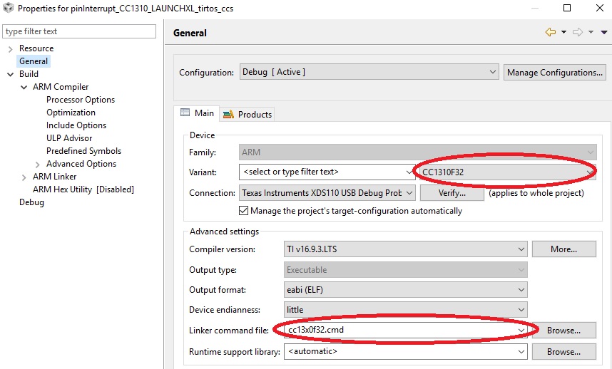
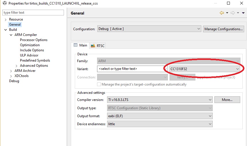
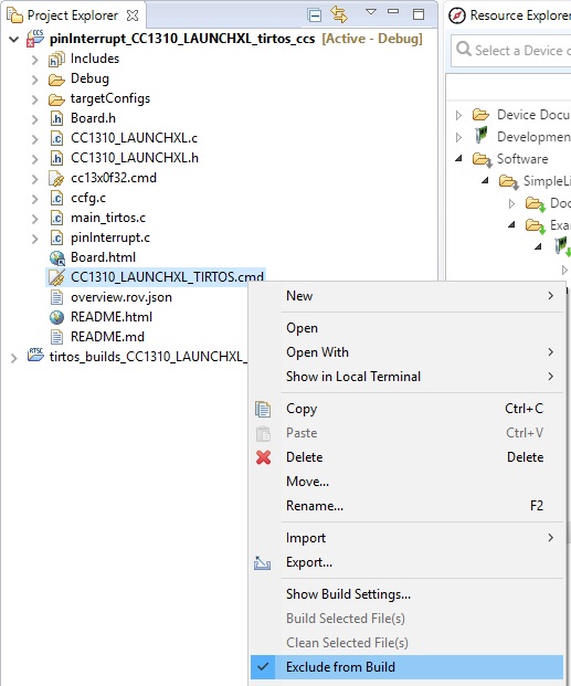
I just made a custom PCB based on the CC1310F32 and I want to compile the project and generate the HEX file to download into the chip. I change the device to CC1310F32 but I don't know whether I need to leave the linker command file as it is or I will have to change it to cc13x0f32.cmd.

Anyone can advise on this?

  • Hello Kian,
    Please change the linker cmd file to match your custom board profile. In this case cc13x0f32.cmd
    Regards,
    Prashanth
  • In addition you have to remove the .cmd file you don't need (selecting a new linker file adds the linker file but doesn't delete the original one.)
  • Hi all. Thanks for the reply. Somehow changing the linker cmd file gave me errors.

    Changing it to cc13x0f32.cmd gave me the following errors:

    <Linking>
    "../cc13x0f32.cmd", line 78: error #10263: FLASH memory range has already been specified
    "../cc13x0f32.cmd", line 78: error #10264: FLASH memory range overlaps existing memory range FLASH
    "../cc13x0f32.cmd", line 80: error #10263: SRAM memory range has already been specified
    "../cc13x0f32.cmd", line 80: error #10264: SRAM memory range overlaps existing memory range SRAM
    error #10010: errors encountered during linking; "rfWakeOnRadioTx_CC1310_LAUNCHXL_tirtos_ccs.out" not built


    If I use the default CC1310_LAUNCHXL_TIROS.cmd, the program compiles successfully. But when I load the program onto the chip, it doesn't seem to work.


  • Hi all,

    This is what I have tried so far. I decided to use an unmodified example from Resource Explorer in CCS. I am using  SimpleLink CC13X0 SDK - v:1.40.00.10 with a custom PCB and a CC1310F32RHBT.

    From Resource Explorer, I imported the example Software -> SimpleLink CC13x0 SDK - v:1.40.00.10 -> Examples -> CC1310 LaunchPad -> TI- Drivers -> pinInterrupt -> TI-RTOS -> CSS Compiler。

    Next, on CCS project explorer, I right click on the project folder, go to properties, and changed the device to CC1310F32. I also changed the Linker command file to cc13x0f32.cmd.

    Next I right click on the tirtos_builds_CC1310_LAUNCHXK_release_ccs folder, select properties, and also changed the device to CC1310F32:

    After that, under Project explorer, I right click on the file CC1310_LAUNCHXL_TIROS.cmd and select "exclude from build".

    Next I build the project.

    And I have 6 errors. Can anyone help? Thanks!

  •  I also tried using the CC1310_LAUNCHXL_TIROS.cmd file instead and changed the starting address to:

    #define FLASH_BASE 0x0
    #define FLASH_SIZE 0x8000
    #define RAM_BASE 0x20000000
    #define RAM_SIZE 0x4000

    The program compiles successfully. I download the program onto the PCB using Flash Programmer. However, the program is not working. The LED is not responding to the push button.

  • Reading a different thread you also posted in: Do you have a F32 device in RGZ (7x7) or RHB (5x5)
  • Hi TER,

    I have a RHB device. I think keeping the original CC1310_LAUNCHXL_TIROS.cmd and just editing the flash size will work. That's what everyone is saying on the forum.

    As for why my program downloads but doesn't work, I am suspecting it because I do not have a 32kHz crystal connected.  I will try to add a crystal or use the internal oscillator (by editing the ccfg file). Hopefully it will work. And I can't figure out why I am unable to debug. This is the error I am getting when I try to debug:

    Cortex_M3_0: Can't Run Target CPU: (Error -2134 @ 0x0) Unable to control device execution state. Reset the device, and retry the operation. If error persists, confirm configuration, power-cycle the board, and/or try more reliable JTAG settings (e.g. lower TCLK). (Emulation package 6.0.628.1)

    Cortex_M3_0: JTAG Communication Error: (Error -1170 @ 0x0) Unable to access the DAP. Reset the device, and retry the operation. If error persists, confirm configuration, power-cycle the board, and/or try more reliable JTAG settings (e.g. lower TCLK). (Emulation package 6.0.628.1)

    I have 5 wires connected from my custom PCB to a LaunchPad as a programmer (3.3V, GND, RESET, TMS, TCK). There is a thread discussing this:

    What is the implication of the 22uF capacitor and 6.8uH inductor connected to DCDC_SW? I do not have the inductor and just put a 0 ohm resistor in its place.

  • If you use a RHB device, have you adjusted the board file to reflect the pinout?

    I don't have access to a board with the combination of packet size and board size that you use so I'm not able to test anything in my end.

    If you use SmartRF Studio, is it then possible to control your board?
  • Hi. I manage to solve all the problems. I can download and debug now. I added a 32k crystal and 12pF capacitors and shorten the wires from my PCB to the LaunchPad for programming. Somehow the long wires give problems to the debugging.

    I did not change the board.h file. Instead, in the CC1310_LAUNCHXL.h file, I set pins that are not available in the RHB package (eg. IOID15 and above) to PIN_UNASSIGNED.