


Other Parts Discussed in Thread: CC1190, CC1310
Hi,
I am working with the two 433 MHz 1350 Launchpads LAUNCHXL-cc1350-4. I modified them so that I use the SMA connector output for the 433 MHz link. Really great that SMA's are available on the Launchpad. I use a 433 MHz rubber ducky antenna.The system works well. Checked it all using SmartRF Studio. I managed to get the SimpleLink Academy Simple Tx and Simple Rx to work pretty much straight away.
The next thing I would like to do is to add some external components such as an RF switch, external PA and external LNA (in order to extend range). Please see the block diagram below.

This is where it got a bit hard for me. Im basically trying to understand how I can separate the Tx and Rx paths. From reading the technical documents it seems that external PA and LNA's can be controlled using IOs.
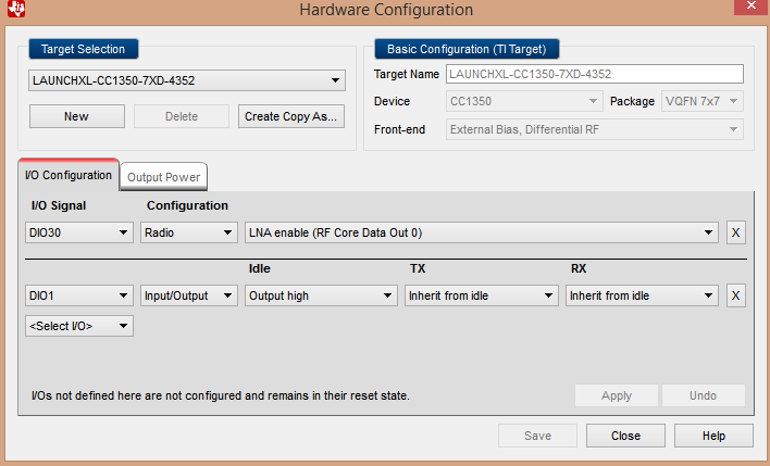
To do that I saw that in SmartRF studio I can go to "Configure Target..." and set that up. So i did.
I went back to my initial setup of having 2 launchpads communicating with each other. block diagram below of my experiment:
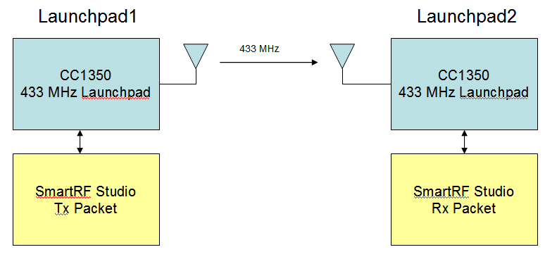
For the launchpad running Tx Packet (Launchpad 1) I setup the following:

For the launchpad running Rx Packet (launchpad 2) I setup the following:
If I understand this correctly when i press Start and run Packet Tx and Packet Rx on 2 different launchpads I should see some sort of transition from LOW to HIGH or HIGH to LOW on DIO30 when the PA is active on Launchpad1 and when the LNA is active on Lauchpad 2.
To observe that I connected an oscilloscope and had ch1 observe launchpad1 DIO30 and had ch2 observe launchpad2 DIO30. I got no transitions at all, it was constantly at logic '0', i couldnt see the control signals for the external PA and LNA toggled on either launchpads on DIO30. The system is working, the data is going through, plz see below (RSSI is high because the boards are 20 cm apart):

Could you please help me with this? What am i doing wrong here? Why cant i see any control signals for the external PA and LNAs on DIO30 on either launchpad? Thanks.
Stevan


