This thread has been locked.

If you have a related question, please click the "Ask a related question" button in the top right corner. The newly created question will be automatically linked to this question.

CC1120: Optimizing CC1120 modulation parameters for best reception, sensitivity, BER and range ...

Part Number: CC1120
Other Parts Discussed in Thread: CC1101

Hi Ti experts,

We are users of the CC1120 Transceiver ICs for a few years now and very satisfied with the flexibility and performance for our applications on custom boards.

One issue that has cropped up recently is the choice of optimal frequency deviation dF vs RX receiver bandwidth Rx-BW for 4GFSK based systems.

Doing a quick scan of available literature one comes across the formula for 2-FSK for the Occupied Bandwidth of : 2 x dF + Br = OBW (where dF is the peak frequency deviation and Br is the binary bitrate). This will be slightly less for 2-GFSK.

So my question relates to M-ary FSK system of which the CC112X is capable of. Notably 4GFSK will have twice the effective bitrate and should have a larger OBW than 2GFSK, therefore optimizing (or matching) the Receiver filter Rx-BW is crucial to get best S/N and BER for maximum overall range and sensitivity.

Unfortunately we are beyond the evaluation board and SmartStudioRF as we have more or less used the values recommended by the software for the 10K - 20K symbol rate range, the preamble and sync-word etc. This was really done at the start and the values recommend are more or less the ones s=used for the radio initialization. The optimization we seek is really on a more general level and needs to be applied to our custom board for the application.

One way I have tried doing is to generate a BER output from a CC1120 link from one transmitter Tx to a receiver Tx (configured from our custom boards – displayed on the OLED and available as a USB output to TeraTerm)), adding a 20 m coaxial between for isolation and some 110dB attenuation between the two Tx and Rx. So the only path for the transmitted signal is via the coax and the attenuator (the Tx and Rx PCBs being inside metal cases for isolation - yes, leakage and unwanted interference is significant at such low signals levels).

The symbol rate Sr and packet length and format is fixed, however by tweaking the attenuation to get to a low level BER (say < 3%) then trying various modulation index m, vs frequency deviation dF, vs receiver bandwidth Rx-BW we are hoping to find a minimum point somewhere for a certain configuration of these modulation parameters.

The current results are not quite as expected which makes me think of the spectrum of 4GFSK signal from a CC112X, similarly as estimated for a 2-FSK signal above OBW = 2 x dF + Br. Some literature mentions a formula of 6 x dF + 4 x Sr = OBW (where Bit rate Br = 2 x Sr Symbol rate for 4-FSK). However for a 10K symbol rate and 15KHz deviation, it would give us a rather large spectrum comparatively - about 130KHz, but we see a Receiver BW requirement of a lot less actually only around < 50KHz (and works OK even with slightly less). Thgis makes me think the 4GFSK generated by the CC112X is much more spectrally efficient than the formulas for OBW would make us think. This 4GFSK modulation format has a better spectral efficiency because of Gaussian shaping, OK, but I did not expect less than half that !! Actually with a RX-BW of around 100KHz (a good compromise to fit most of the 130KHz estimated OBW) the range is terrible and the BER is >50%. I assume the S/N is degraded significantly as the receiver B/W is actually larger than required and too much noise enters the system …

so my question(s) :

  1. Can you please recommend a similar formula (or some way) to estimate the OBW specifically of a CC112X radio in 4GFSK mode, to allow users to better estimate/predict OBW and consequently the optimum receiver bandwidth Rx-BW to use for the purpose of optimizing range, BER etc for a given system. It may be that the CC112X Gaussian shaping, and or other signal processing in the CC112X transmitter does not quite match the ideal “Matlab” generated spectra that give the OBW = 6 x dF + 4 x Sr prediction available in some literature.
  2. Can you point to some application notes that treat in more detail 4GFSK systems such as the CC112X as the ones seen are mainly based on the 2FSK or similar...
  3. How would you recommend an optimization on this level (modulation index m vs dF, vs Rx-BW) should be done, given you know the Ti radio performance at a higher level than most users in the general public ? Any recommendation that may assist us ?

Thanks in advance and regards,

Mke Marin

  • Mke,

    1. Actually we find that using Matlab to simulate the occupied bandwidth is better that just using a first order approximation like "Carson's Rule". These approximations do not tell the entire picture.

    2. There are some good material online, but a couple of general items about our devices is that they perform best at above a modulation index of 0.5 because they are not coherent demodulators. We typically use modulation indexes of 0.7 to 1.0 (you can see that in our SmartRF Studio). The device also performs well at above a modulation index of 1 but the RX bandwidth becomes wider than minimum required and therefore the RX sensitivity is slightly degraded.

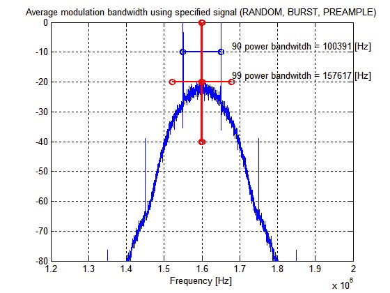
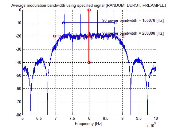
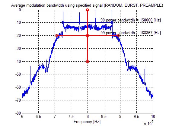
    3. There is a interesting thing about 2FSK and 4FSK, 4FSK is not necessarily better (more narrow). Here I have made an simulation of 2FSK versus 4FSK at 100kbps (100ksps for 2FSK and 50ksps for 4FSK) so that the effective data rate is the same.

      The first image is 100kbps 2FSK with a modulation index of 1.0


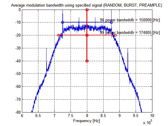
    4. The next slide is 100kbps (or 50ksps) 4FSK also with a modulation index of 1.0

    From these two simulations you will find that 4FSK actually occupies more RF bandwidth than 2FSK when configured for the same modulation index.

    Regards,
    /TA

  • Also note that for 4(G)FSK the modulation index for the inner symbols has to be large enough for the receiver to manage to demodulate. Since the inner symbols is 1/3 of the outer symbols the resulting signal bandwidth could be fairly wide.

    We have typically used 4GSK in two cases:
    - FCC part 90 or similar where we need to get as much data as possible through in a given bandwidth.
    - High datarates since the symbol rate has a max and the datarate can then be doubled using 4GFSK compared to 2GFSK.
  • Hi,

    Ok thanks for the info. I assume (but correctly if I'm wrong) to calculate de modulation index H, you used the following general formula : H = (2 x dFpeak) / ( Sr x (M - 1))

    where dFpeak is the outer deviation, Sr = symbol rate, and M = alphabet size (2 or 4 for 2FSK or 4FSK etc.)

    If we take a 10K symbol rate, for a given fixed path attenuation, I measure BER minima at H = 0,666 for 4GFSK with a 30KHz filter. There also seems to be low BER errors at H = 1,0 approximately but with a larger filter set at 60KHz. Even though both seem to be "touching" on low levels of BER for same conditions, our preference in the real world would be the one with lower receiver filter bandwidth, around 30KHz, due to better noise performance and cross-talk between channels etc. Only slight drawback is possible errors due to the CC112X PLL crystal tolerance ppm, but there we chose a very low (2,5ppm) tolerance 40MHz TCXO, and the radios are usually calibrated one-by-one in production to reduce carrier variation to less than 1KHz ...

    The eventual application is for En 300 220, and FCC 47 part 15.

    As a sanity check, would these above values H = 0,666 and H = 1 make sense to you ? Would one over the other make more sense ? Should we even consider H > 1,50 ?

    From your answer I assume the 4GFSK spectra would be very similar for the same modulation H = 1 or would the bandwidth be significantly more narrow ?

    Also, I assume for 4GFSK on the CC112X, the inner deviation is 1/3 of the peak outer deviation by default, and probably fixed in hardware ??

    Regards,

    Mike Marin

  • Hi TA,

    Further to your suggestion to use a modulation index H between 0,7 and 1,0, it would seem also necessary to match the receiver filter to the spectrum generated by the particular modulation index H. In other words, for a format of 4GFSK (to which my question relates in general) and a range of modulation indexes of 0,7 to 1,0 (which you advise) which would be more or less optimal in terms of minimum spectrum required for transmission, what is a matched filter range, (say like a “Rx filter bandwidth index” range) to go with the respective modulation indexes ?

    Using too small a filter would lose demodulation capacity, and having too much filter bandwidth would degrade S/N as the filter is larger than necessary for demodulation, so there should be a compromise somewhere. Can you recommend this matching between modulation indexes H, and filter "Rx bandwidth indexes" for optimal reception (eventually in noisy environments noise would degrade the channel but …) for the CC112X radio transceivers ??

    I think my filter BW question is the other half of the partially answered question, to getting optimal transmissions in eventually noisy environments. We would appreciate your advice on this matter for this particular device please.

    Regards,

    M Marin

  • For RX required RX BW:
    ----
    Required RX filter bandwidth can be approximated as :Signal BW + 4*ppm xtal*Frequency of operation , where Signal BW of = Data rate + 2 x frequency deviation.

    Example: 38.4 kbps data rate and +/-19.2 kHz deviation gives Signal BW of38.4 + 2 x 19.2 = 76.8 kHz

    For modulation index m= 1, the frequency separation, which is 2 x frequency deviation, is equal to the data rate. I.e m = 2 x frequency deviation / data rate
    ---
    Here the signal bandwidth is an approximation. To find the actual RX BW:
    - Use Matlab or similar to calculate it
    - Measure it
  • TER said:
    For RX required RX BW:
    ----
    Required RX filter bandwidth can be approximated as :Signal BW + 4*ppm xtal*Frequency of operation , where Signal BW of = Data rate + 2 x frequency deviation.

    Example: 38.4 kbps data rate and +/-19.2 kHz deviation gives Signal BW of38.4 + 2 x 19.2 = 76.8 kHz

    For modulation index m= 1, the frequency separation, which is 2 x frequency deviation, is equal to the data rate. I.e m = 2 x frequency deviation / data rate
    ---
    Here the signal bandwidth is an approximation. To find the actual RX BW:
    - Use Matlab or similar to calculate it
    - Measure it

    Hi TER,

    Thanks for your suggestions. I think for 1-FSK this is a good approach and would certainly use it when necessary, however for 4-GFSK these "of the back of an envelope" calculations don't give us enough accuracy for what we're looking at. Take for instance the graph above for 4FSK, with a modulation index H =  1 and 50Ks/s the deviation dF = 75KHz, then gives 50 + 2 x 75 = 200 KHz is the calculated signal bandwidth using the carson's rule estimate.

    Then for a 2,5ppm TCXO crystal at 869 MHz say,  I calculate a Rx BW = 200 + 4 * 2.17 = 208.7 KHz allowing for crystal tolerances and aging. The MATLAB spectrum for 4-FSK show a 99% signal bandwidth of 174,805 KHz and at 90% of 150,000 KHz. I would assume with certainty the spectrum is even more efficient for Gaussian 4-FSK (but do not know by how much), so all I am saying is that going by simple carson's rule for 4GFSK can easily lead us to over-estimating the required filter bandwidth.

    I thought it may be a good start to ask Ti directly regarding the choice of Rx BW they would recommend for the CC112X chip, other than what is available in most literature. So if the estimation is to coarse I guess measuring it could be another good way to go....

    Regards, Mike

  • Data rate + 2 x frequency deviation works fairly good on 2-FSK doing quick estimates but for other modulations simulations or measurements are the way to go to find the signal bandwidth. 

  • Hi,

    Yes for 2-FSK I would agree, but perhaps an overestimate for GFSK. However the issue here is the Receiver bandwidth and shape for the CC112X. This is not something readily available in any literature, and my question relates to best choice of Rx BW for a given modulation index for 4GFSK for the CC112X. We had used previously the CC1101 which have another filter shape altogether ... So simulations of the Rx filter of the CC112X is quite out of the scope for us really as you can see.

    Regards, Mike
  • Not sure if I understand your last post. What I have indicated you can simulate is the modulation bandwidth since the 2-GFSK and 4-GFSK shape from CC112x is fairly close to text book. The RX filter can be regarded as brick wall since the order of the filter is high so no need to simulate the RX filter.
  • TER said:
    Not sure if I understand your last post. What I have indicated you can simulate is the modulation bandwidth since the 2-GFSK and 4-GFSK shape from CC112x is fairly close to text book. The RX filter can be regarded as brick wall since the order of the filter is high so no need to simulate the RX filter.

    Hi TER,

    Yes thanks, I think it helps knowing to treat the filter as a "brick wall filter".

    thanks and regards,

    Mike

  • Mike, 

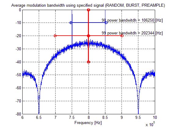
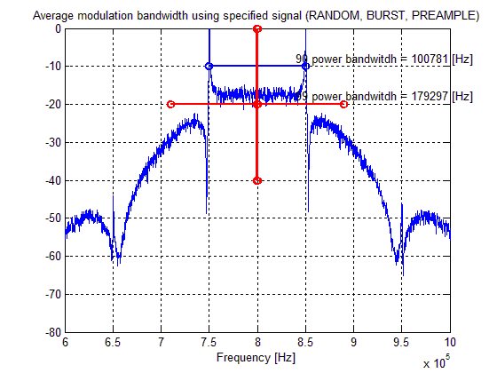
    I just re-read my post from earlier and I wrote 2FSK, where I actually meant to write 2GFSK. I am sorry about that, so I will now post all 4 combinations for your reference. Also note that my initial post was using a BT=0.5 which is not supported by these device, so for this repost I have modified the Gaussian BT=1.0 as per what the device actually transmit.

    1. 100kbps 2FSK
    2. 100kbps 2GFSK
    3. 100kbps (50 k symbols/s) 4FSK
    4. 100 kbps (50ksymbols/sec) 4GFSK

    Sorry about the initial error, hope this helps.

    Regards,
    /TA

  • Mike,

    It took me a long time to get my head around the "Brick Wall Filter" concept. Coming from an analog background, I kept getting hung-up on the behavior of LRC filters which a Brick Wall Filter only approximates. It's actually a pure software beast which processes the IQ data and can be programmed for virtually any passband limit. If the IQ data is <HzMin or >HzMax, that's it; nothing to model or think about.

    --
    Jay Zebryk
  • Hi TA,

    Yes thanks for clearing that up for me. There is a significant difference between the 4FSK and 4GFSK for the 99% power bandwidth, almost 10% less bandwidth. Good to know this as we are trying to minimize the occupied bandwidth without degrading the channel.

    I thought I'd do some typical BER measurements with a 544 bits pseudo randome cyclic pattern on our custome transceiver at a 18kS/s and here are some typical results for various filters. Not immediately obvious the relation beween optimal deviation dF, Rx Filter BW and least bit-errors.

    I guess wie'll be doing this for all relevant speeds and filters. Unfortunately we don't  have a good Matlab model of the Ti transceivers, and if we were to build one we'd have no way to verify it is actually representative, so you're right, measurements are best way afterall to find these "sweet-spots" if we want to ensure optimal configuration.

    Cheers, M Marin

  • - Note that on CC1120 you can use FB2PLL giving you a higher efficient RX BW without increasing the noise bandwidth. Thee the User Guide for more details.
    - Reminder: When you decide a RX BW you also have to take into account the crystal (initial ppm, temp variation, aging)