This thread has been locked.

If you have a related question, please click the "Ask a related question" button in the top right corner. The newly created question will be automatically linked to this question.

CC1310: EVM with Whip antenna not communicating with custom board with PCB antenna

Part Number: CC1310

Hi.

First of all, I want to say that my radio knowledge is not very advanced, so perhaps I will say some nonsense and surely I can't see the point where any advanced radio pro can just in seconds.

After developing a SW for my project with CCS to test in my CC1310 EVM's on SmartRF06 boards and verifying all worked as intended, I have designed and manufactured a custom board based on the CC1310 2-Layer 7x7 v1.3.3 reference design (CC13xxEM-7XD-7793), but adding the IPC 0850BM14E0016T from Johanson Technology to eliminate passive components and using the PCB antenna. All intended to work in 868MHz.

I loaded the SW in one of my custom board (PCB antenna) verifying it works correctly in debug mode and tried to communicate with one of the EVM board (with the whip antenna). I did this the first because I trusted the tested EVM and I didn't trusted the radio part of my own board, so if something failed I would know it was my custom board. And this is what actually happened: there wasn't any communication between both boards.

I tested every combination between the 2 EVM's versus my 3 custom boards (switching HUB and remote node functions) but nothing worked. I tested directly with my SW and also through SmartRF Studio packet transmission.

I tested again communications between the 2 EVM's themselves: worked as It should.

Then, with no hope (why it should work?), I tried to communicate 2 of my custom boards. Surprise! It worked. My custom boards communicate between themselves but not with the EVM!!!

They did with an RSSI of -40dBm, not the -15dBm of the EVM, but I expected that because the use of a 2 layer board, PCB antennas and the lack of tunned PI netwok.

I am very happy cause my boards work, but the big question is: why they don't work against the EVM's? If I want to put a whip antenna in a new custom design for the HUB to improve the range or simply reduce the consumption, I need to answer that question.

What I first thought was that my custom boards could be transmitting in a different frequency from the planned one due to my design. To tested I used SmartRF Studio in Continuous Tx/Rx mode, changing the frequency and using one custom board and one EVM. Surprisingly I detected -40dBm signal in the 868MHz and only there, with both boards established to that frequency.

So there is no deviation in frequency in my boards. Then, why I can detect a signal with SmartRF Studio in Continuous Tx/Rx mode in 868MHz, but I can't make them communicate through the SmartRf Studio in Packet Tx/Rx mode (nor with my SW) in that or any other frequency? What Continuous mode of SmartRf Studio does transmit and detect?

Thank you very much in advance!

Regards,

Juan Pablo Novo

  • More or less all cases where customers have a boards of type A and boards of type B and A communicate with and B communicate with B but not A with B have been due to frequency offset.

    You state that you only see a signal if you use 868 MHz, how much did you try to skew the frequency?
  • Hi, Ter.

    Sorry for the delay. I was out for a while...

    Thanks to your comment, I have done a finer search with SmartRF Studio and I did manage to discover that the offset of my boards is 70KHz up from the configured frequency.

    So I could communicate my custom boards with the EVM boards, setting the EVM board frequency to 868.070 MHz with a RSSI of only -15dBm.

    Knowing that, I can solve any similar problem setting the right frequency in the program code.

    But I wish to know why this offset happens to try to avoid it in future designs. Is it related to the use of a 2 layer board and its design? The design of the PCB antenna? Perhaps the lack of a tuned PI netwok? Another thing?

    Again, thank you very much!
  • A frequency offset is only due to the reference clock, in other words that the xtal operate on too low or too high frequency. This again is typically caused by wrong load cap compared to what the xtal require.

    A common cause on CC1310 boards is that customers mount external load caps without turning off the internal load cap array (see processors.wiki.ti.com/.../CC26xx_Tips_and_Tricks)
  • I have followed the reference design as close as I could, so I didn't mount external load caps. I did use same Epson Crystal and I read and followed the recommendations from the Crystal Oscillator and Crystal Selection for the CC26xx and CC13xx Family of Wireless MCUs document (SWRA495A–December 2015–Revised December 2015).

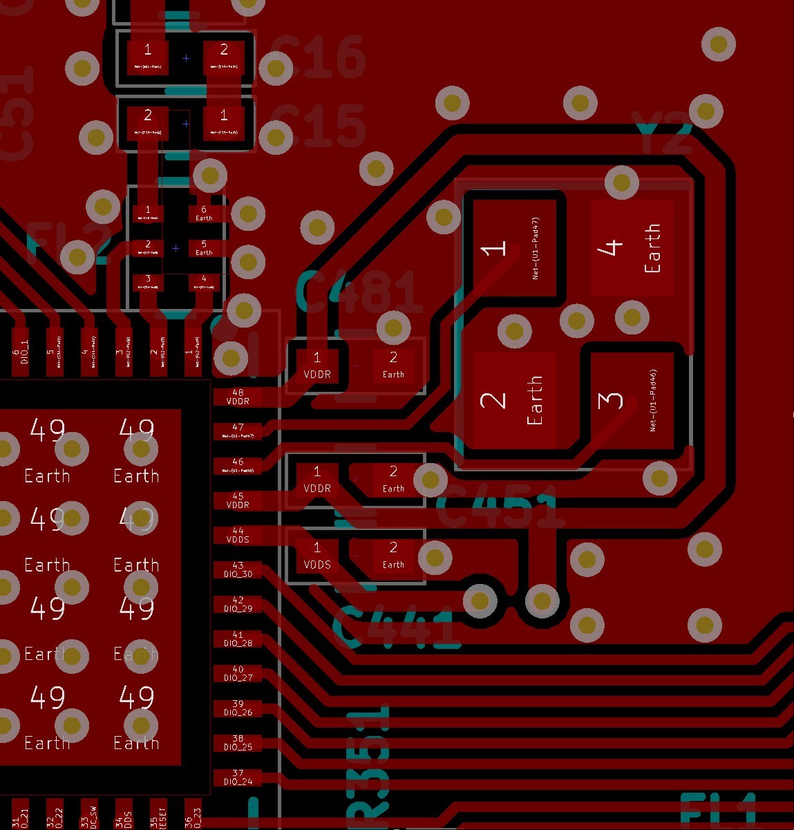
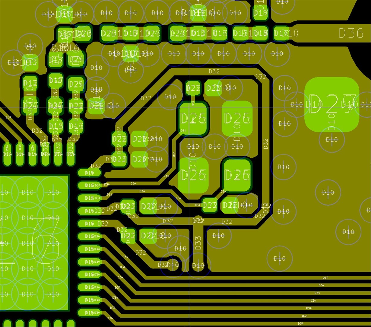
    My custom PCB design in this area is nearly the same but, of course, there are minimal differences (not included the PADs for DNM capacitors, for example). I have attached custom and reference design of the crystal area so you can compare. There is a solid ground plane under this area in my design.

    Can they affect enough to modify the loading capacitance on the Crystal? If not, and as I don't use external load caps, what other factors can affect?

    On the other side, how adjusting the internal loading capacitance through programming affects the final frequency? Increasing CL increase the frequency? Vice versa? I didn't find an equation in your link or in the document I mention before that shows the relation. No other way other than trying and seeing the effects?

    I think changing CL is a smarter way to solve the problem than setting a not real frequency in the code to get the expected frequency.

    Crystal area in custom design:

    Crystal area in reference design:

  • In the newest SmartRF studio you can adjust the cap array described in processors.wiki.ti.com/.../CC26xx_Tips_and_Tricks and the document you are referring to without doing any programming making it a bit easier to adjust the Cload. Increasing the Cload will reduce the frequency. I don't see any reason why the frequency should be 70 kHz off in your case. Are you able to borrow a spectrum for an hour and so and verify the frequency offset? Now you are basically measuring the offset between two PCBs, if you want to adjust the offset you need to know the offset on your PCB and only that offset.
  • I will download the last SmartRF and try it.

    I was using the EVM's from TI as a reference as I thought they work accurately as expected :), but you are right, it should be better to measure the RF signal of each board with a spectrum analyzer. I will try to get one and test it. I will tell you the results.

    Thank you very much!
  • I have tested the boards with a spectrum and I have checked the following:
    - The EVM boards from TI transmit in the expected frequency of 868MHz. The main frequency peak changes from 867.97 to 868.03, being usually in 868.00MHz
    - My custom boards transmit with an offset of 80KHz over the 868MHz: The main frequency peak changes from 868.05 to 868.11, being usually in 868.08MHz
    So this confirms pretty well the 70KHz offset I discovered with SmartRF Studio.
    I will try to adjust the offset of my boards changing the Cload through the new SmartRF Studio
  • I still don't understand why you get the offset since your layout looks good (btw, do you have the same stack-up as in the ref design?) but as long as you know the offset you can adjust for it with modifying the cap array.
  • My stack-up is the same as the reference design: 2 layers of 0.035mm of copper in a 0.73mm FR-4 dielectric.

    I have tried tuning the cap-array, but I have found that with the maximum positive delta value of 10, I only get a frequency reduction of 20KHz. So I am not able to reduce the 70KHz I need. In the other side, with the maximum negative delta value of -27, I get a frequency increment of 80KHz.

    The available frequency range with the cap-array is not enough to solve my problem, so it seems I will have to stick to change the frequency in the code, using not real values.
  • It could sound like you are using a xtal with a different CLoad spec than you think you are using. Have you tried to swap xtal with a board that send on the correct frequency?
  • Why do you think so? Is it something wrong with the range of frequencies I can get adjusting the Cload? Should I be able to get a negative offset of 70KHz? What is the expected adjustable range?

    I will try to verify the crystal model with my board manufacturer. If they verify that it is the right one on paper, I will think about exchanging the crystals.
  • It looks like you have followed the ref design fairly well. Our board has a frequency that is more or less spot on and if you are actually use the same xtal you should see the same on your board. 70 kHz frequency offset a bit more than I normally see.
  • I have just received the answer from my board manufacturer: By mistake they have bought and place the TSX-3225 24.0000MF10Z-C3 (18pF) instead of the TSX-3225 24.0000MF15X-AC3 (9pF)!!!

    This explains everything. They will buy the right ones and change them in my boards.

    Thank you very much for your clues and help resolving this mystery!
  • Good that you managed to figure it out. Assembly errors could be a bit tricky to find.
  • Crystals were changed and now everything works as it should. Thank you again!