This thread has been locked.

If you have a related question, please click the "Ask a related question" button in the top right corner. The newly created question will be automatically linked to this question.

CC1190: Using the CC1190 with the Atmel AT86RF212B

Part Number: CC1190
Other Parts Discussed in Thread: CC1101, CC1120

Hi All 

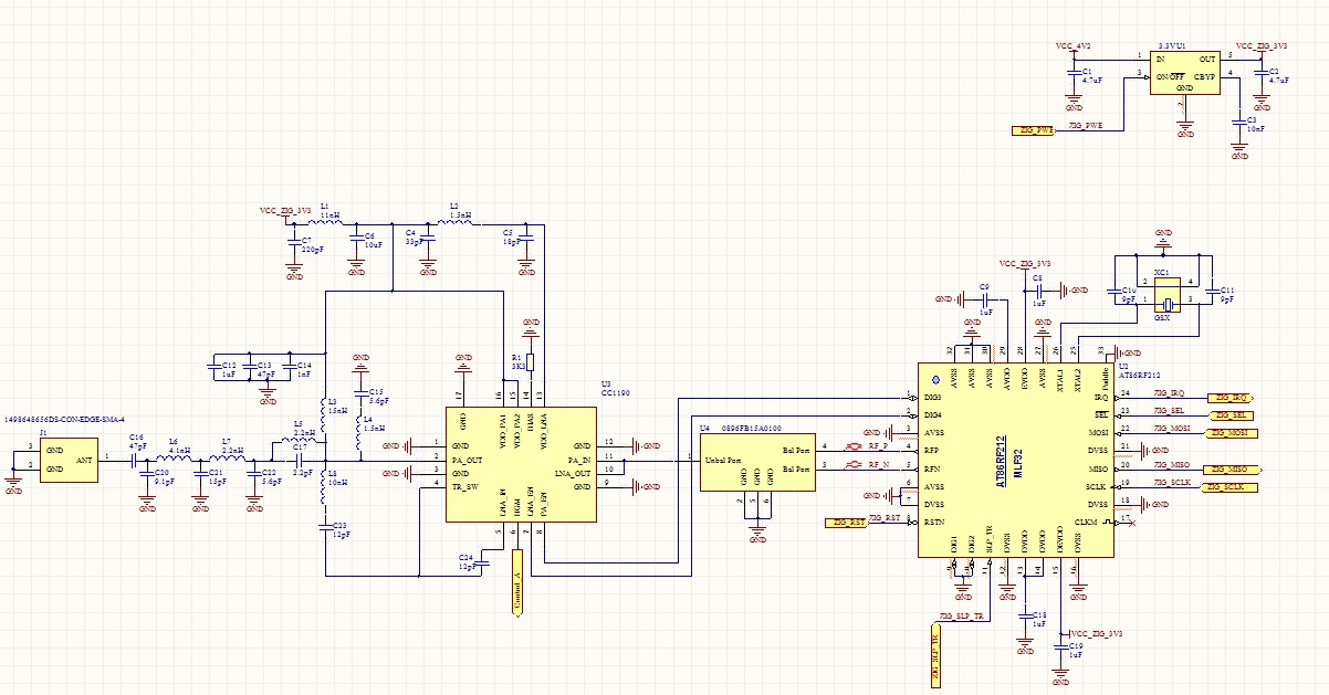
I would like to use the CC1190 front with the ATMEL AT86RF212B. 

We can not change the transceiver as the design is completed but we require a greater transmission range, therefore would like to introduce a power amplifier and hoping to change the modulation to BPSK 20Kb/s.

I was recommend to use Skywork but would prefer to use TI parts as the lead time are far more better.

Can you some please advice me on the following :

  1.  Is my design that i have attached correct? It is based on the CC1101_CC1190EM development board. Is there improvement that can be made?

  2. The aim is to achieve maximum range, but to for certain regulations we might need to keep the power output less then its maximum. Is there away to do some form of bypass to avoid maximum power? or my inputting a power between -25db to 11 dbm(AT86RF212B), would that also effect the power output of the CC1190.

  3. I have used a balun with a filter between the AT86RF212B and CC1190. As per Atmels recommendation i have used 0896FB15A0100 from Johanson Technology. 

  4. Is there anything else that i need to keep in mind to insure that is this no additional noise or issue that could arise using any EMC testing?

Just out of curiosity, what sort of range has other designs achieved?  

Please find my design attached. 

Thank YOu

  • 1) I would recommend using the CC1120 - CC1190 reference design as a starting point. Also add a SAW filter between the radio and CC1190 (or at least a footprint) since spurious/ harmonics also gets amplified.

    2) www.ti.com/.../swra393c.pdf gives an indication of how the output power varies as a function of input power. Also look into if you should use a series cap between the radio and CC1190.

    In the CC1120-CC1190 ref design a couple of notches are used for maximum attenuation of the 2. harmonic. The exact frequency for these are dependent on layout and it could be that the notch should be adjusted slightly in your design.

    For low datarates and line of sight the range will mainly be limited by the earth curvature.
  • 1) I will look at the reference design , the Balun also includes a filter. What effect will that filter have and would it be any conflict to the SAW. Can you recommend a good SAW filter to use if this is necessary with the filter included in the Balun?  As per Atmel, they recommend no filter would be necessary as the Balun includes one.

    2)What is the advantage of the series cap?  Would i be correct in saying that this will be between the output of the Balun and Front Device. 

    In regards to earth curvature, its not necessary to have such great distance, i was think more a less few KM?

    Thanks

  • Different filtering is required for 11 dBm and 27 dBm output power. For 11 dBm the filter in the balun is likely adequate to filter the spurious and harmonics but these will be amplified by CC1190 and may need further filtering.

    For series cap, does the balun have a AC coupling or is a DC level at the output that may not be ideal for CC1190?

    The excel sheet here: e2e.ti.com/.../375556 can be used for range esimates. You have to estimate the output power and sensitivity for your combination.
  • What page do i look in the pdf at to find the output power achieved from input power?

    Is there a recommend SAW filter that can be use? Is this filter on the output of the filter?

    I think the balun has a DC, as the datasheet does shown there is 100pF 0603 capacitor in series on the output. I am using the www.johansontechnology.com/.../0896FB15A0100.pdf

    I am note sure what impact this will have with CC1190, as you mentioned it might not be ideal?
  • Just to confirm, is the reference design you are referring to the CC1120-CC1190 Booster Pack
  • Just read the schmatic and BOM .

    See that B3725 is recommended for 868Mhz
  • For your reference i have attached my updated schematic . Am i correct that the SAW filter is between balun and CC1190?

  • Looks good.
  • Would there any filtering between the AMP and the Antenna?

    My intention is keep any noise or emission very low, so i have not regulation or performance issues?

    The CC1190 has a low output and high output, can the device also be configured to work in as bypass mode?

    Can you also send me a link to see what output power can be achieved based on input, as this will be important to change the output power in area that have certain regulation .

    Thanks

  • What do you define as filtering? As the reference design shows and the app note describe both impedance matching and filtering is done between the CC1190 output and the antenna connector.

    CC1190 does not have a bypass mode. If this is needed you have to do this with RF switch in addition.

    The app note I have linked to give an indication of which output power to expect for which input power. Since you are using a different radio the numbers will be somewhat different and hence you have to generate your own power table doing measurements.