This thread has been locked.

If you have a related question, please click the "Ask a related question" button in the top right corner. The newly created question will be automatically linked to this question.

LAUNCHXL-CC1310: One CC1310 as TX,three CC1310 as RX. Why does three Rxs not receive the same packet at the same time?

Part Number: LAUNCHXL-CC1310
Other Parts Discussed in Thread: CC1310

Hi Team,

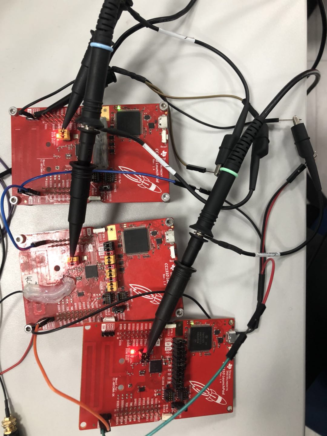
       Customers feedback a problem. There were 4 CC1310 Launchpad.

        One CC1310LP is as TX device, running the demo rfPacketTx_nortos; while another three CC1310LP all are as RX device, running the demo rfPacketRx_nortos.

          CC1310 TX device sent a packet in the air.  Why does three Rx devices not receive this packet at the same time? And sometimes it delay a lot.

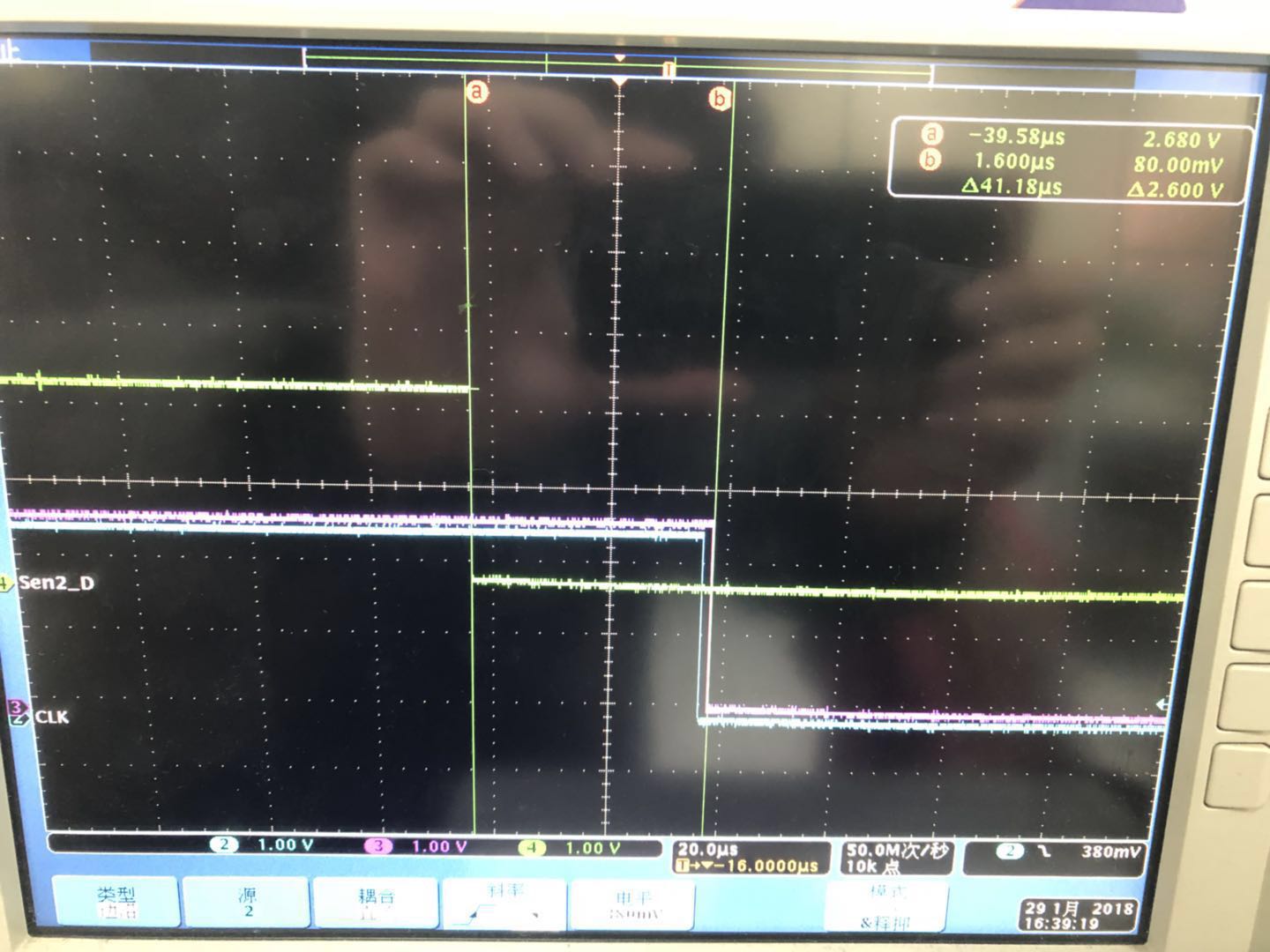
We do a test, when Rx device receive the packet from Tx device, Rx device code will go into the callback function. In the callback function, we make a pin output from high to low level. 

Let's see below Waveform. Do you have any suggestions? Thank you!


  • Is it always the same device that reads first? Or do they change order?

    The sleep function that the radio calls causes interrupts to be accurate only down to 10uS.  I think your receivers clocks are probably out of sync enough to cause the buffered receive interrupt to raise at different times.

    Can you try monitoring your LNA active pin instead of turning an LED on after the hook?

    PINCC26XX_setMux(PinHandle, PinWhateverPinYouWant, PINCC26XX_MUX_RFC_GPO0); // Route out LNA active pin
    

  • Hi,

    a small difference of +-1/4 symbol rate is expected. But 40µs is indeed huge. I think the root cause is that something preempts the software interrupt (SWI) which is responsible for the callback. Possible that the clock subsystem is running a SWI as well. In the No-RTOS kernel implementation, there is not much you can do because SWI scheduling is non-preemptive. In TI-RTOS, SWIs are implemented preemptive and you can increase the RF driver's HWI and SWI priority above the Clock system.

    Does it work as expected in TI-RTOS?

    If you want to achieve time synchronization between devices and set an IO exactly at the same time, some more work is needed.

    • Send a sync message from the master to the slaves with absolute timing. The sync message must include a time stamp in the payload, for instance, the tx start time.
    • The slaves receive the timestamp message and by substracting the timestamp in the packet payload from their own RX timestamp, they know the exact difference between their own radio timer (RAT) and the master's RAT.
    • Based on that, they can now load an unused RAT channel with a common future timestamp and program the RAT to set an IO pin on a compare match.
    • This should allow very accurate setting of IO pins.
    • Unfortunately, the RAT API in the RF driver until SimpleLink SDK 1.60 is a mess and not user-friendly. There will be new user-friendly functions in the next SDK 1.70.

    This post shows how to use EasyLink to send and receive timestamp messages. It explains a two-way synchronization, but in your application, it is enough to do it one way. It is much more work to achieve the same result with raw proprietary commands.

  • Hi Richard,

    Whether TIRTOS or NORTOS, the problem still appear. Do you have another way to deal with this problem on NORTOS? Sync way is complex. Thanks!
  • Hi Chris,

    they change order!
  • When you use this signal:

    PINCC26XX_setMux(PinHandle, PinWhateverPinYouWant, PINCC26XX_MUX_RFC_GPO0); // Route out LNA active pin

    Assuming that you configured your RX command to stop after one packet, do you still see 40µs deviation when the signal goes low (packet reception finished)? What PHY mode are you using at which symbol rate?

  • Test the LNA, but can you also show us the code around your RX command? Are you receiving in a loop with a timeout? Are you waiting forever?
  • Hi  All,

            Based on the project of rfPacketRx_CC1310_LAUNCHXL_nortos_ccs,   I call the API what you said,  

    PINCC26XX_setMux(ledPinHandle, Board_PIN_LED2, PINCC26XX_MUX_RFC_GPO0); // Route out LNA active pin

    but when it receive the packet, the Board_PIN_LED2(LNA pin) keep high level. Do you know why? 


        Bellow is my code :

    /***** Includes *****/
    /* Standard C Libraries */
    #include <stdlib.h>
    
    /* TI Drivers */
    #include <ti/drivers/rf/RF.h>
    #include <ti/drivers/PIN.h>
    #include <ti/drivers/pin/PINCC26XX.h>
    
    /* Driverlib Header files */
    #include DeviceFamily_constructPath(driverlib/rf_prop_mailbox.h)
    
    /* Board Header files */
    #include "Board.h"
    
    /* Application Header files */ 
    #include "RFQueue.h"
    #include "smartrf_settings/smartrf_settings.h"
    
    /***** Defines *****/
    #define RX_TASK_STACK_SIZE 1024
    #define RX_TASK_PRIORITY   2
    
    /* Packet RX Configuration */
    #define DATA_ENTRY_HEADER_SIZE 8  /* Constant header size of a Generic Data Entry */
    #define MAX_LENGTH             30 /* Max length byte the radio will accept */
    #define NUM_DATA_ENTRIES       2  /* NOTE: Only two data entries supported at the moment */
    #define NUM_APPENDED_BYTES     2  /* The Data Entries data field will contain:
                                       * 1 Header byte (RF_cmdPropRx.rxConf.bIncludeHdr = 0x1)
                                       * Max 30 payload bytes
                                       * 1 status byte (RF_cmdPropRx.rxConf.bAppendStatus = 0x1) */


    /***** Prototypes *****/
    static void callback(RF_Handle h, RF_CmdHandle ch, RF_EventMask e);
    
    /***** Variable declarations *****/
    static RF_Object rfObject;
    static RF_Handle rfHandle;
    
    /* Pin driver handle */
    static PIN_Handle ledPinHandle;
    static PIN_State ledPinState;
    
    /* Buffer which contains all Data Entries for receiving data.
     * Pragmas are needed to make sure this buffer is 4 byte aligned (requirement from the RF Core) */
    #if defined(__TI_COMPILER_VERSION__)
        #pragma DATA_ALIGN (rxDataEntryBuffer, 4);
            static uint8_t rxDataEntryBuffer[RF_QUEUE_DATA_ENTRY_BUFFER_SIZE(NUM_DATA_ENTRIES,
                                                                     MAX_LENGTH,
                                                                     NUM_APPENDED_BYTES)];
    #elif defined(__IAR_SYSTEMS_ICC__)
        #pragma data_alignment = 4
            static uint8_t rxDataEntryBuffer[RF_QUEUE_DATA_ENTRY_BUFFER_SIZE(NUM_DATA_ENTRIES,
                                                                     MAX_LENGTH,
                                                                     NUM_APPENDED_BYTES)];
    #elif defined(__GNUC__)
            static uint8_t rxDataEntryBuffer [RF_QUEUE_DATA_ENTRY_BUFFER_SIZE(NUM_DATA_ENTRIES,
                MAX_LENGTH, NUM_APPENDED_BYTES)] __attribute__ ((aligned (4)));
    #else
        #error This compiler is not supported.
    #endif
    
    /* Receive dataQueue for RF Core to fill in data */
    static dataQueue_t dataQueue;
    static rfc_dataEntryGeneral_t* currentDataEntry;
    static uint8_t packetLength;
    static uint8_t* packetDataPointer;
    
    
    static uint8_t packet[MAX_LENGTH + NUM_APPENDED_BYTES - 1]; /* The length byte is stored in a separate variable */
    
    /*
     * Application LED pin configuration table:
     *   - All LEDs board LEDs are off.
     */
    PIN_Config pinTable[] =
    {
        Board_PIN_LED2 | PIN_GPIO_OUTPUT_EN | PIN_GPIO_LOW | PIN_PUSHPULL | PIN_DRVSTR_MAX,
    #if defined __CC1352R1_LAUNCHXL_BOARD_H__
        Board_DIO30_RFSW | PIN_GPIO_OUTPUT_EN | PIN_GPIO_HIGH | PIN_PUSHPULL | PIN_DRVSTR_MAX,
    #endif
    	PIN_TERMINATE
    };
    
    /***** Function definitions *****/
    
    void *mainThread(void *arg0)
    {
        RF_Params rfParams;
        RF_Params_init(&rfParams);
    
        /* Open LED pins */
        ledPinHandle = PIN_open(&ledPinState, pinTable);
        if (ledPinHandle == NULL)
        {
            while(1);
        }
    
         PINCC26XX_setMux(ledPinHandle, Board_PIN_LED2, PINCC26XX_MUX_RFC_GPO0); // Route out LNA active pin
        //IOCPortConfigureSet(Board_PIN_LED2, IOC_PORT_RFC_GPO0, IOC_STD_OUTPUT);
    
        if( RFQueue_defineQueue(&dataQueue,
                                rxDataEntryBuffer,
                                sizeof(rxDataEntryBuffer),
                                NUM_DATA_ENTRIES,
                                MAX_LENGTH + NUM_APPENDED_BYTES))
        {
            /* Failed to allocate space for all data entries */
            while(1);
        }
    
        /* Modify CMD_PROP_RX command for application needs */
        RF_cmdPropRx.pQueue = &dataQueue;           /* Set the Data Entity queue for received data */
        RF_cmdPropRx.rxConf.bAutoFlushIgnored = 1;  /* Discard ignored packets from Rx queue */
        RF_cmdPropRx.rxConf.bAutoFlushCrcErr = 1;   /* Discard packets with CRC error from Rx queue */
        RF_cmdPropRx.maxPktLen = MAX_LENGTH;        /* Implement packet length filtering to avoid PROP_ERROR_RXBUF */
        RF_cmdPropRx.pktConf.bRepeatOk = 1;
        RF_cmdPropRx.pktConf.bRepeatNok = 1;
    
        /* Request access to the radio */
        rfHandle = RF_open(&rfObject, &RF_prop, (RF_RadioSetup*)&RF_cmdPropRadioDivSetup, &rfParams);
    
        /* Set the frequency */
        RF_postCmd(rfHandle, (RF_Op*)&RF_cmdFs, RF_PriorityNormal, NULL, 0);
    
        /* Enter RX mode and stay forever in RX */
        RF_EventMask terminationReason = RF_runCmd(rfHandle, (RF_Op*)&RF_cmdPropRx, 
                                                   RF_PriorityNormal, &callback, 
                                                   RF_EventRxEntryDone);
    
        switch(terminationReason)
        {
            case RF_EventCmdDone:
                // A radio operation command in a chain finished
                break;
            case RF_EventLastCmdDone:            
                // A stand-alone radio operation command or the last radio 
                // operation command in a chain finished.
                break;         
            case RF_EventCmdCancelled:
                // Command cancelled before it was started; it can be caused
                // by RF_cancelCmd() or RF_flushCmd().
                break;
            case RF_EventCmdAborted:
                // Abrupt command termination caused by RF_cancelCmd() or 
                // RF_flushCmd().
                break;  
            case RF_EventCmdStopped:
                // Graceful command termination caused by RF_cancelCmd() or 
                // RF_flushCmd().
                break;  
            default:                
                // Uncaught error event
                while(1);
        }
        
        uint32_t cmdStatus = ((volatile RF_Op*)&RF_cmdPropRx)->status;
        switch(cmdStatus)
        {
            case PROP_DONE_OK:
                // Packet received with CRC OK
                break;
            case PROP_DONE_RXERR:
                // Packet received with CRC error
                break;
            case PROP_DONE_RXTIMEOUT:
                // Observed end trigger while in sync search
                break;
            case PROP_DONE_BREAK:
                // Observed end trigger while receiving packet when the command is
                // configured with endType set to 1
                break;
            case PROP_DONE_ENDED:
                // Received packet after having observed the end trigger; if the 
                // command is configured with endType set to 0, the end trigger 
                // will not terminate an ongoing reception
                break;
            case PROP_DONE_STOPPED:
                // received CMD_STOP after command started and, if sync found, 
                // packet is received
                break;
            case PROP_DONE_ABORT:
                // Received CMD_ABORT after command started
                break;
            case PROP_ERROR_RXBUF:
                // No RX buffer large enough for the received data available at 
                // the start of a packet
                break;
            case PROP_ERROR_RXFULL:
                // Out of RX buffer space during reception in a partial read
                break;
            case PROP_ERROR_PAR:
                // Observed illegal parameter
                break;
            case PROP_ERROR_NO_SETUP:
                // Command sent without setting up the radio in a supported
                // mode using CMD_PROP_RADIO_SETUP or CMD_RADIO_SETUP
                break;
            case PROP_ERROR_NO_FS:
                // Command sent without the synthesizer being programmed
                break;
            case PROP_ERROR_RXOVF:
                // RX overflow observed during operation
                break;
            default:
                // Uncaught error event - these could come from the
                // pool of states defined in rf_mailbox.h
                while(1);
        }
        
        while(1);
    }
    
    void callback(RF_Handle h, RF_CmdHandle ch, RF_EventMask e)
    {
        if (e & RF_EventRxEntryDone)
        {
            /* Toggle pin to indicate RX */
           // PIN_setOutputValue(ledPinHandle, Board_PIN_LED2,!PIN_getOutputValue(Board_PIN_LED2));
    
            /* Get current unhandled data entry */
            currentDataEntry = RFQueue_getDataEntry();
    
            /* Handle the packet data, located at &currentDataEntry->data:
             * - Length is the first byte with the current configuration
             * - Data starts from the second byte */
            packetLength      = *(uint8_t*)(&currentDataEntry->data);
            packetDataPointer = (uint8_t*)(&currentDataEntry->data + 1);
    
            /* Copy the payload + the status byte to the packet variable */
            memcpy(packet, packetDataPointer, (packetLength + 1));
    
            RFQueue_nextEntry();
        }
    }
    

  • Can you provide the packet you are transmitting and also a copy of your smartRF settings so we can see how your radio is configured?

  • smartRF settings is default. Nothing is changed when I load the project on SDK.
  • The signal is kept high since the example uses repeat mode:

    RF_cmdPropRx.pktConf.bRepeatOk = 1;
    RF_cmdPropRx.pktConf.bRepeatNok = 1;

    To have it to exit RX after a packet is received, you should set repeat mode to 0.

    Siri
  • You could also try changing this line:

    RF_EventMask terminationReason = RF_runCmd(rfHandle, (RF_Op*)&RF_cmdPropRx, 
                                                   RF_PriorityNormal, &callback, 
                                                   RF_EventRxEntryDone);

    to this:

    RF_EventMask terminationReason = RF_runCmd(rfHandle, (RF_Op*)&RF_cmdPropRx, RF_PriorityNormal, NULL, 0);

    This will insure power management isn't applied to the Cortex-M3 and should provide the most deterministic results.

    You will need to change up how you process your packet, but as a test this should help identify if it is processor latency or something else.