This thread has been locked.

If you have a related question, please click the "Ask a related question" button in the top right corner. The newly created question will be automatically linked to this question.

CC1310: Sensor controller power consumption

Part Number: CC1310
Other Parts Discussed in Thread: ENERGYTRACE, , CC1350

Hello!

Then Sensor controller is enabled, current consumption rises to 2uA in Standby mode.  

I run SC task every second. Even then SC Execution task is empty (zero lines of code) - current rises to 2 uA in Standby mode on cc1310 4x4. On cc1350LP all ok - 1 uA.
Then i run SC task every 10 seconds on cc1310 4x4 - current drops to 1 uA. Without SC (and before first execution of SC task) current - 0.7 uA.

I inserted this code in "pinStandby" example:

scifOsalInit();

scifInit(&scifDriverSetup);

scifStartRtcTicksNow(0x000A0000);

scifStartTasksNbl(BV(SCIF_EMPTY_TASK_ID));

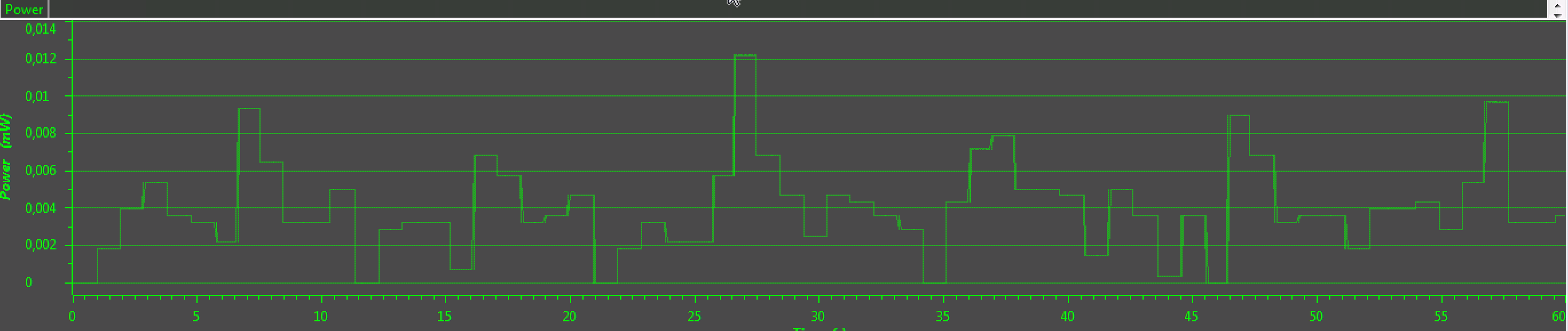
Power log from EnergyTrace for SC task executed every 10 seconds:

My SC empty project: 8637.Empty.scp.zip

  • Hi, generally speaking: The CC13xx uses a recharge pulse algorithm to determine the interval between recharge pulses in standby, and the parameters for this algorithm is updated on every M3 wake up.
    If your application just uses SC without starting M3, the initial recharge pulse interval values are used - and these values are conservative (start-up) values.
    In such user case you can benefit from waking up the M3 a number of times (doing NOPs) before (or during) the initial SC activity. This will update the interval parameters and can give a lower power consumption figure.

    The CC1310 4x4, is that a custom board?

  • Hello! Thank you for the answer!
    As i said, i use "pinStandby" example for tests. It's wakes up every 5 seconds.
    CC1310 4x4 - is a board, produced using this TI Ref. design:  SimpleLink CC1310 IPC 4-Layer 4x4 Differential 779-930 MHz v1.0.1 Design Files

    Also, current consumption depends from SC task run frequency:   

    scifStartRtcTicksNow(0x00010000)  =  2uA

    scifStartRtcTicksNow(0x000A0000)  =  1uA

  • Hi, can you post the whole project instead of just the xml project file so I can test it here.
  • Hi, the board files for the project you sent is for a 7x7 package.
    You wrote "current rises to 2 uA in Standby mode on cc1310 4x4. On cc1350LP all ok - 1 uA."

    Are you using the board files for a 7x7 package for your 4x4 package project?
  • Yes, i commented pins in BoardGpioInitTable, that is not exists in 4x4 package.
    Anyway, no pins is used in project.
  • Actually you do use pins in the project. Check lines 45-51 in file pinStandby.c:

    /* Led pin table */
    PIN_Config LedPinTable[] =
    {
        Board_PIN_LED0    | PIN_GPIO_OUTPUT_EN | PIN_GPIO_LOW | PIN_PUSHPULL | PIN_DRVSTR_MAX, /* LED initially off */
        Board_PIN_LED1    | PIN_GPIO_OUTPUT_EN | PIN_GPIO_LOW | PIN_PUSHPULL | PIN_DRVSTR_MAX, /* LED initially off */
        PIN_TERMINATE                                                                      /* Terminate list */
    };
    

    These pins are mapped to IOID_6 and IOID_7, which does exist for the 4x4 package.
    I am not able to compile your project for some reason, so I am not able to recreate what you see per now.

  • This variable (LedPinTable) not used in project. As i can see on page 8 of cc1310 datasheet, IOID_6 and IOID_7 exists for the 4x4 package.
    You can recreate my situation using this steps:
    1. Install "pinStandby" example from cc1310 SDK 1.6
    2. Create Empty task (or any other task) in Sensor Controller Studio
    3. Import this task to "pinStandby" example

  • Any update?
  • Hi, no I am not able to reproduce the issue on my bench. Can you provide a working project which showcases what you are seeing.
  • It's strange, that you can't compile my project, i just installed it from SDK 1.6 example with small changes. What error messages from CCS compiler do you get? May be you do not have TI-RTOS installed in your CCS?

    Did you tried this?:
    You can recreate my situation using this steps:
    1. Install "pinStandby" example from cc1310 SDK 1.6
    2. Create Empty task (or any other task) in Sensor Controller Studio
    3. Import this task to "pinStandby" example

  • Hi, I copied your sce files into a new pinStandby project and copied the content of your pinStandby.c. It's working now.
    I will continue with measurements Monday.
  • Hello!
    Any update?
  • Hello! Did you made measurements?
  • Hi, yes I did. I measured 'your' project on a launchpad, it draws 2.2uA (for Vdds = 3.3V):

  • Hello!
    It's good that you see the problem. In accordance with the cc1310 datasheet, current must be 0.95 uA.
    You can do the same measurements on cc1350 LP. Current will be 0.95 uA (as described in datasheet).
    How to fix this problem?
  • Rustem: Could you point to the exact section in the datasheet that indicate that you should get 0.95 uA when you have a SCE process running?
  • On the first page of datasheet:

    – Sensor Controller, One Wakeup Every Second
    Performing One 12-Bit ADC Sampling: 0.95 μA

  • I have been trying to find out which code that has generated this number. As far as I understand it the CM3 has to be woken up at least 10 times to get the re-charge pulse generation to be optimal. I intended to do some measurements last week but the instrument was busy.
  • Any update?
  • Any update?
  • This ended in the "to do" stack which normally is too full...

    From what I have been able to find out is that the number in the datasheet (0.95 uA) was measured with bare metal code with a early version of the power driver. I was able to get the current down to 1.5 uA using this code:

    void taskFxn(UArg a0, UArg a1) {
        PIN_Handle hLedPins;
    
        // Enable LED pins
        hLedPins = PIN_open(&ledPinState, pLedPinTable);
    
        // Initialize the Sensor Controller
        scifOsalInit();
        scifOsalRegisterCtrlReadyCallback(scCtrlReadyCallback);
        scifOsalRegisterTaskAlertCallback(scTaskAlertCallback);
        scifInit(&scifDriverSetup);
        scifStartRtcTicksNow(0x00010000 / 1);
    
        // Configure and start the Sensor Controller's ADC window monitor task (not to be confused with OS tasks)
        scifTaskData.adcWindowMonitor.cfg.adcWindowHigh = 800;
        scifTaskData.adcWindowMonitor.cfg.adcWindowLow  = 400;
    
    //    Semaphore_pend(Semaphore_handle(&gateSCStask), BIOS_WAIT_FOREVER);
        scifStartTasksNbl(BV(SCIF_ADC_WINDOW_MONITOR_TASK_ID));
    
        // Main loop
        while (1) {
    
            // Wait for an ALERT callback
            Semaphore_pend(Semaphore_handle(&semScTaskAlert), BIOS_WAIT_FOREVER);
    
            // Clear the ALERT interrupt source
            scifClearAlertIntSource();
    
            // Indicate on LEDs whether the current ADC value is high and/or low
            if (scifTaskData.adcWindowMonitor.output.bvWindowState & SCIF_ADC_WINDOW_MONITOR_BV_ADC_WINDOW_LOW) {
                PIN_setOutputValue(hLedPins, Board_GLED, 1);
            } else {
                PIN_setOutputValue(hLedPins, Board_GLED, 0);
            }
            if (scifTaskData.adcWindowMonitor.output.bvWindowState & SCIF_ADC_WINDOW_MONITOR_BV_ADC_WINDOW_HIGH) {
                PIN_setOutputValue(hLedPins, Board_RLED, 1);
            } else {
                PIN_setOutputValue(hLedPins, Board_RLED, 0);
            }
    
            // Acknowledge the alert event
            scifAckAlertEvents();
        }
    
    } // taskFxn
    
    void clkFxn(UArg arg0)
    {
        static int counter = 0;
    
        if (++counter > 1)
        {
            clkHandle = Clock_handle(&clkStruct);
            Clock_stop(clkHandle);
    
            /*
             * Start Sensor Controller tasks
             */
    
            Semaphore_post(Semaphore_handle(&gateSCStask));
            //scifStartTasksNbl((1 << SCIF_LOW_POWER_CAPACITIVE_SENSING_TASK_ID));
            //scsTaskStarted = TRUE;
        }
    }
    
    
    int main(void) {
        Task_Params taskParams;
        Clock_Params clkParams;
    
        // Initialize the PIN driver
        PIN_init(BoardGpioInitTable);
        CC1310_LAUNCHXL_shutDownExtFlash();
        //CC1310_LAUNCHXL_initGeneral()
    
        // Configure the OS task
        Task_Params_init(&taskParams);
        taskParams.stack = myTaskStack;
        taskParams.stackSize = sizeof(myTaskStack);
        taskParams.priority = 3;
        Task_construct(&myTask, taskFxn, &taskParams, NULL);
    
        /* Construct BIOS Objects */
    
        Clock_Params_init(&clkParams);
        clkParams.period =  500000/Clock_tickPeriod;
        clkParams.startFlag = TRUE;
    
        /* Construct a one-shot Clock Instance */
        Clock_construct(&clkStruct, (Clock_FuncPtr)clkFxn,
                        1500000/Clock_tickPeriod, &clkParams);
    
    
        // Create the semaphore used to wait for Sensor Controller ALERT events
        Semaphore_Params semParams;
        Semaphore_Params_init(&semParams);
        semParams.mode = Semaphore_Mode_BINARY;
        Semaphore_construct(&semScTaskAlert, 0, &semParams);
        Semaphore_construct(&gateSCStask, 0, &semParams);
    
        // Start TI-RTOS
        BIOS_start();
        return 0;
    
    } // main
    

    In the adc_window_monitor example.

    I a real application the CM3 will wake up and doing some processing at intervals which will set the recharge pulse algorithm. This is in this example simulated by having a clock object before the SCE starts. 

  • Thank you for your attention!
    I'm also achieved 1.5uA by using evhSetupTimerTrigger() inside Sensor Controller. But it still too much for me.