This thread has been locked.

If you have a related question, please click the "Ask a related question" button in the top right corner. The newly created question will be automatically linked to this question.

CC1120: Japan ARIB STD-T108

Part Number: CC1120
Other Parts Discussed in Thread: CC1200, CC1310

Hello,

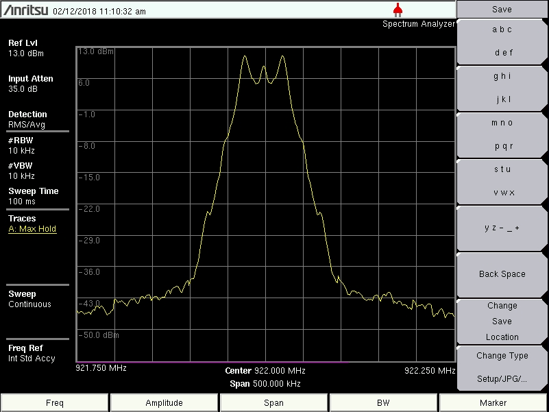
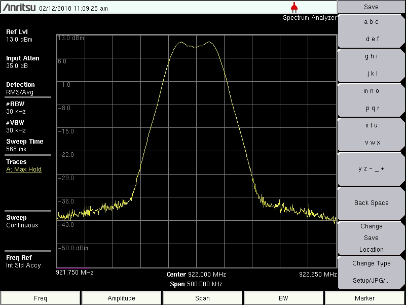
I am verifying my CC1120 designed radio under Japan ARIB STD-T108 "Low Power Radio Stations" category but cannot meet the channel mask requirement (ACP mask) because of having some out of band emissions/spurious when in transmit mode. I am setting the radio at Po=13dBm, f=922MHz, 2GFSK.

TX and RX unwanted emissions pass the requirements though. 

Couple of questions,

1- Can CC1120 pass the ARIB STD-T108 "Low Power Radio Stations" with regards to the ACP mask and occupied BW? (CH-BW=200KHz, Pout=20mW and f=922MHz or so)

2- What settings in CC1120 will help the meet the ACP mask requirements and have less out of channel emissions in TX mode? (i.e. 2GFSK modulation, max bit rate=? deviation=? and etc.)

3- When testing the radio is it be valid to transmit packet data instead of CW? Is it possible that sending packet data instead of CW transmission could cause some out of band emissions/spurious?

(PS: SWRA445 is a TI report about this test for CC1200).

Thanks,

-Reza


  • As www.ti.com/.../swra445.pdf shows 2 unit channels have to be used in some cases to pass the ACP tests. You are not writing which datarate and how many unit channels you use in tests.

    Why do you use CC1120 and which datarate are you planning to use? If you plan to use a higher datarate that about 50 kbps I would recommend using CC1200 (or CC1310). I believe it's a requirement to test with a modulated signal (not packets, a continuous PN9 stream)
  • Hi TER,
    Thanks a lot for the helpful reply. I am transmitting at 50 kbps (50ksps, 2GFSK). I need to have a single channel at 922MHz or a different frequency from "Low Power Radio Station" group.
    Q1) Do you mean it is OK to have one single channel at 922MHz and occupy 2 adjacent channels (2*200KHz=400KHz) instead of 200KHz, which means n=2 instead of n=1. I asked the RF Test house engineer today during the test and he mentioned it's not allowed although I believe he wasn't the sure.
    Q2) I can lower the bit rate, what bit rate you think CC1120 is good to set to to meet the ACP test? Do you think I need to lower the power as well? (In the time being I need to use CC1120 but for the final product I will go with your suggestion and will use CC1200 or CC1310.)
    Thanks,
    -Reza
  • On CC1200 I also measured ACP for 50 kbps (3.3.2 see www.ti.com/.../swra445.pdf ) and I would expect CC1120 to give very similar results. Since CC1200 has good margin at the channels edge this should be the same for CC1120.

    - Could you post the ACP plot you have done that you fail?
  • HI TER,
    I've attached the un-modulated and modulated snapshots for
    fc=922MHz, 2GFSK, 50ksps
    Q1) It seems the un-modulated carrier BW is too much is there any way to make it narrower in CC1120 settings or this is normal?
    Q2) If I go with n=2 it seems I can pass the T108, is that correct?
    Q3) Looking at the spectrum do you think the background is too much, I mean the signal floor level outside the carrier BW? Shouldn't it be sharper?
    Thanks,
    -Reza
  •    sorry attachments didn't come through, attaching again

  • The question is if you are using the correct RBW. T-245 dictate 1 kHz for these measurements as far as I can see.
  • Hi TER,
    No as shown in my screen shots I am using RBW=100KHz (VBW=300KHz). If I use RBW=1KHz then peak amplitude will fall and easily will pass the mask but the thing is that peak value will fall as well and wont be 13dBm as shown above. How would I compensate for that.
    Your measurement with CC1200 for -T108 doesn't show the screen shots and the SA RBW and etc.
    Thanks,
    -Reza
  • As I read the spec (T-245) the measurement should be done with a modulated signal (not with a CW as you show in the first plot). Then the peak value should not be an issue.

    I would recommend to read T-245 since this describe how to do the measurements required by T-108.
  • Hi TER,
    Sure. I'll read T-245 although haven't been able to find it on the web yet.

    My 2nd and 3rd snapshots are the modulated signals using the CC1120 random data and register contents are used from SmartRF Studio.
    Since I am showing the SA screenshot in peak save mode it's very smooth but if I put it in normal live mode I can see the frequency deviations on carrier signal.

    Q) Do you mean if I modulate the 2GFSK as in snapshot 2 and 3 and set the RBW=1KHz (VBW=3KHz) I still will get Pout(max) = 13dB?
    I tried this but what saw was that the whole spectrum amplitude dropped.

    As another note STMicro has an appnote about -T108 (AN4953) on page 10/34 under 3.1 they have described RBW=1KHz, VBW=1KHz for ACP measurement, but they have mentioned "In this case and settings measurement limits are adjusted downwards by 10xlog(100KHz/1KHz)=20dB"
    This is what I saw in my measurement this correction factor that I am not sure how to consider it in my measurement to make sure I am doing it correctly.

    Appreciate your Very helpful comments!

    Thanks,
    -Reza

  • As you may have noticed T-245 is very precise on how you should do a measurement. My version is a version translated by TI Japan so I would assume that the page numbers etc could be different from your version. But if you look at "Conditions of equipment" under "Adjacent channel leakage power" it's clearly stated which RBW and VBW to use. The next "Condition of Test equipment " state that the signal shall be modulated.

    The output power doesn't change as a function of RBW. If you look at "OperationProcedure of Measurement Operation" the power is the integral of all datapoints within the unit channel. Here, I used the ACP functionality of the spectrum for the measurements and set the channel equal to the unit channel. In addition, output power is measured differently and has a separate section in T-245.

    It looks like the app note you refer to haven't done the measurement according to T-245. Again, the standard is very clear on how this should be measured.
  •      Hi TER,

    Thank you for the reply.

    I ordered TI CC1120 EM/Smart tRF TrxEB and tested my PCA side by side with TI using the same setup on my SA. I can reproduce the same exact snapshots on SA and like what I said before to check the ACP resuls when I set the RBW to 1KHz signal amplitudes change.

    Here are the settings

    f=922MHz, 2GMSK, 50kbps (50ksps), deviation=25.024414 KHz, Random Data, Continuous mode, P(out)=13dBm

    Your measurements on SWRA445-March 2014 under 3.3.2 Table 14 numbers are your ACP measurements that I cannot reproduce your numbers by using different RBW settings.

    Please advise how could I reproduce your readings or say how could I make sure that I am passing the T108 based on T245.

    I've attached the snapshots for (modulated with random data at different RBW's) which are the same for TI and my PCA.

    Thanks,

    -Reza

  • The numbers in the app note is measured with a built in ACP function in the SA. If your SA doesn't have this functionality you have to measure ACP as described in T-245.

    Not sure what the plots are supposed to show, could you elaborate a bit since the plots are not showing ACP as far as I can see.
  • Thanks TER.
    If you look at one of the snapshots I sent you on this thread last week, I had the SA at RBW=100KHz and also drew the ACP mask on it showing that it cannot pass the the ARIB-T108 ACP requirement.

    You replied that RBW should be set to 1KHz. My reply back was if I set the RBW=1KHz then amplitude of the signal will drop and it will pass the ACP but the peak value of the signal also drops. You didn't agreed on amplitude drop. My recent snapshots show what I mentioned before.

    But it sounds like you have measured using ACP function of the SA.

    I don't have access to TELEC-T245 but based on what you said I thought, I need to use RBW=1KHz but was concerned about amplitude drop in my measurements.

    Thanks,
    -Reza
  • I'm not sure why you are worried about what looks like a amplitude drop. This clause measure ACP, not output power. If you measure ACP as described you will see the energy in the channel (output power) is close to 13 dBm. It's not relevant to look at the peaks when measuring with a low RBW.

    When measuring according to a standard it's important to follow how to measure to the letter.
  • Hi TER,

    Thanks a lot for the reply and clarification.

    For a brand new design using TI sub-GHz radios to meet STD-T108 and have higher speeds (100Kbps or higher), high RX sensitivity (modulation? Is 4GFSK sensitive enough compared to 2GFSK) what CCxxxx RFIC would you recommend?

    Regards,

    -Reza 

  • CC1200 supports up to 500 ksps.

    4-GSK will have lower sensitivity than 2-GFSK. I don't have any exact numbers in front of me since this will be dependent of how the data are compared. But for 4-GFSK the inner symbol deviation is 1/3 of the outer symbol deviation. => To make the signal as easy to demodulate as a 2-GFSK signal the inner symbols on the 4-GSK should be similar to the outer symbols on the 2 GFSK. This again gives a larger signal bandwidth which would require a larger RX BW.
  • Thanks TER!