This thread has been locked.

If you have a related question, please click the "Ask a related question" button in the top right corner. The newly created question will be automatically linked to this question.

CC1101: URGENT: How to validate "value" that come from RSSI and LQI ?

Part Number: CC1101

Hello

I'm using CC1101 and need a procedure to validate result that come from reading of RSSI Register.

Something like follow:

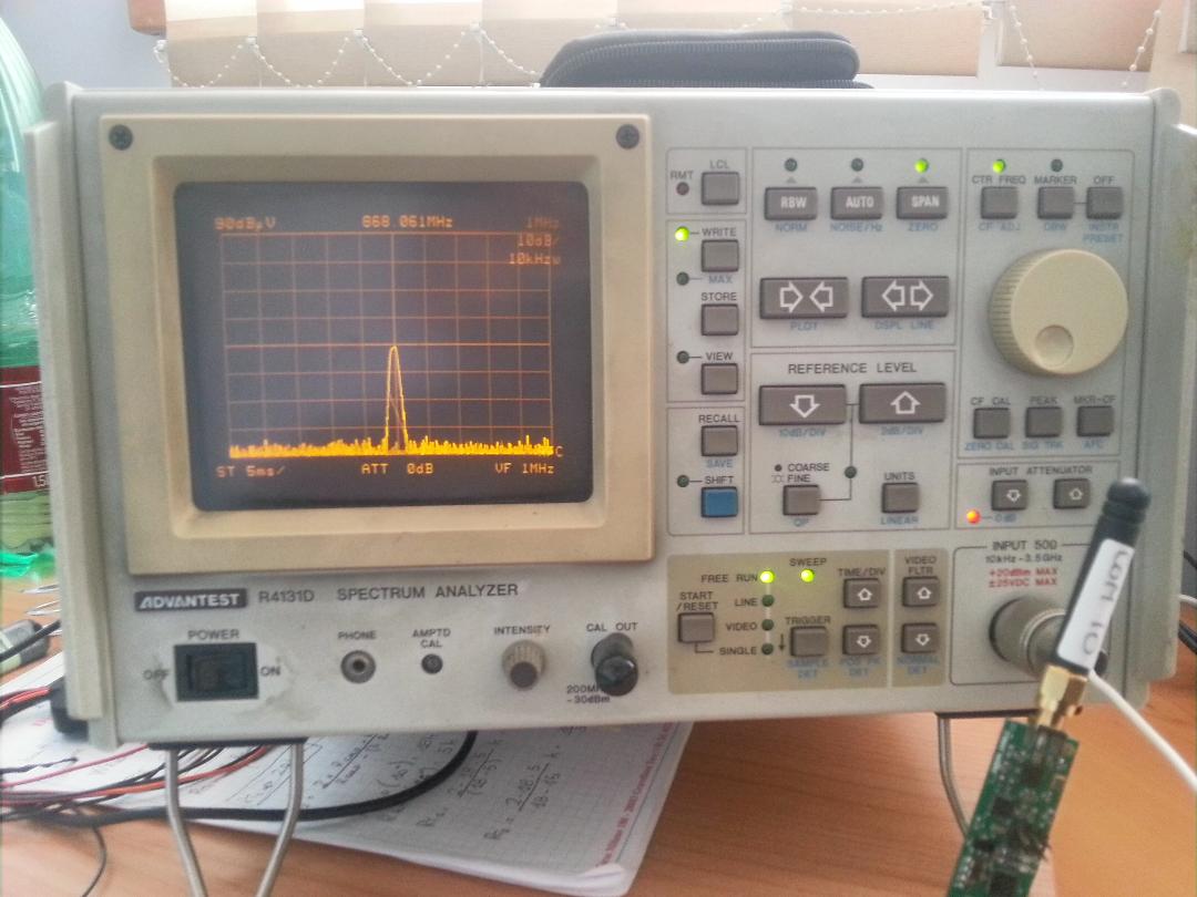
1) set tx power to 0dBm

2) transmit packet every 100mS

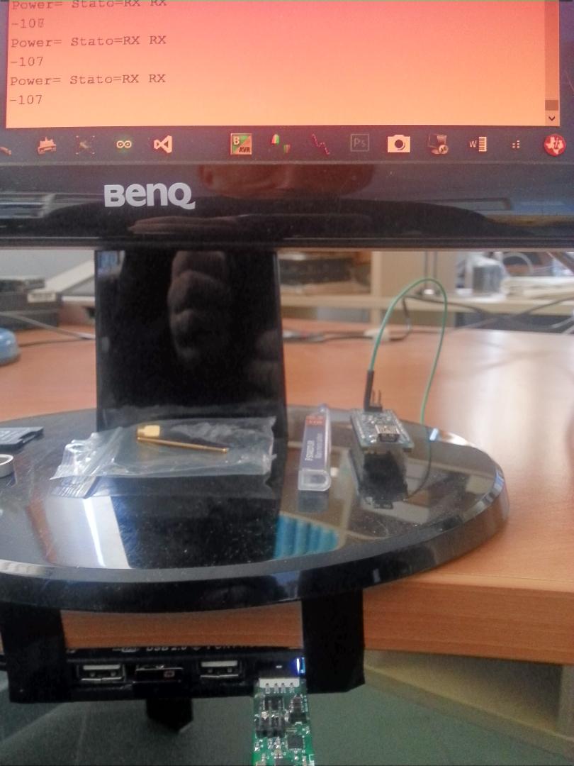
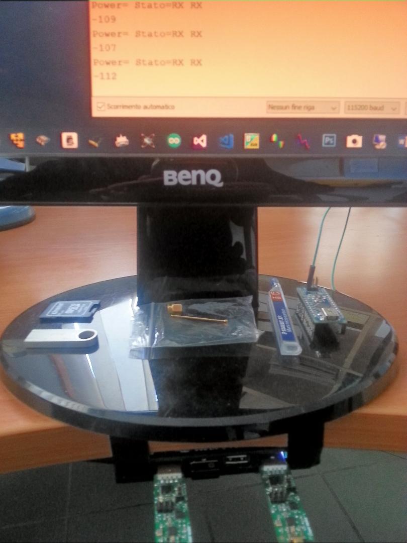
3) read RSSI from register. You should read:

1m  RSSI should be between 70 and 80 dBm 

10m  RSSI should be between 50 and 60 dBm

ecc...

Thanks

  • Not sure I understand what you are after. The RSSI level at a given distance is not a constant and will vary a fair amount as a function how the device is mounted etc.
  • I need a way to verify number taht come from RSSI REGISTER and LQI REGISTER.
    Please show you a way for do this.
    Thanks
  • What do you mean by verify?

    The best test to see if you read out the correct RSSI is to connect a Signal Generator directly through a cable and see if you read out the value you use on the signal generator.

    What is the background for the question?
  • Could you explain better this setup?

  • Do you have a signal generator? Just set this to send a carrier wave (tone) on the frequency you are interested in and connect this to the 50 ohm SMA input on your board. Apply (as an example) -50 dBm and read out the RSSI. If you have set the RSSI offset according to SmartRF Studio you should read out close to -50 dBm from the RSSI register. Set the chip in cont. RX.
  • I have Spectrum Analizer. 

    Which kind of measure I can do with it?

  • For the suggested test you need a signal source with a known signal power. The ideal for this would be a signal generator to do this. As an alternative you can use a CC1101 as TX and use a cable and attenuators to connect this to the DUT. This method is not as accurate since my experience is that it's difficult to know the exact power level.

    A spectrum analyzer is not too useful for this.
  • Hello

    First Problem: read RSSI

    byte CC1101::Power_Level_on_Channel()
    { byte rssi_dec=0; byte rssi_dBm=0; rssi_dec = Read_Status_Register(CC1101_RSSI); if (rssi_dec >= 128) { rssi_dBm = (int)((int)( rssi_dec - 256) / 2) - 74; } else { rssi_dBm = (rssi_dec / 2) - 74; } return rssi_dBm; }

    where Read_Status_Register is:

    byte CC1101::Read_Status_Register(byte addr)
    {
    	byte value, temp;
    
    	temp = addr | READ_BURST;
    	digitalWrite(SS_PIN, LOW);
    	while (digitalRead(MISO_PIN));
    	SpiTransfer(temp);
    	value = SpiTransfer(0);
    	digitalWrite(SS_PIN, HIGH);
    
    	return value;
    }

    Another device transmit on 868MHz:

    My code return alway 228 also when I remove the above transmitter. Why??

    Second problem: Power Down:

    void XOME_CC1101::power_Down()
    {
    	cmdStrobe(CC1101_SIDLE);
    	cmdStrobe(CC1101_SPWD);
    }
    

    where cmdStrobe is:

    void XOME_CC1101::cmdStrobe(byte strobe)
    {
    	digitalWrite(SS_PIN, LOW);
    	while (digitalRead(MISO_PIN));
    	SpiTransfer(strobe);
    	digitalWrite(SS_PIN, HIGH);
    }

    On power supply always see the same current. No drop current happen when power_Down command is sent. Why? 

  • Could you post a plot showing the SPI lines when:
    - You read the RSSI
    - When you try to put the device in power down
  • You can also output one of the CLK_XOSC/n signals on the GDO pins and hence monitor if the crystal stops when trying to put the device in SLEEP.

    Siri

  • For test sleep mode can I check directly on crystal pin XOSC_Q1 or XOSC_Q2?

  • According to 19.3 in the datasheet the voltage regulator to the digital core is turned off when in SLEEP. Meaning that you can measure the voltage on the DCOUPL pin to see if this goes down to 0 V in SLEEP.
  • I have measured crystal on XOSC_Q1 pin and it still oscillate. Voltage on DCOUP is 1.77V.

    Indeed I always see signal on Spectrum Analizer.


    Now since my program is written for Arduino UNO, I think that will be easy for you check it on your lab. Say me if I can send

    Register configuration is take by SmartRF Studio.

    It is the generic second one (1.2K Baud optimized for current consumption).

    In a while I try do record SPI SIGNAL

    Thanks

  • We don't have a Arduino UNO and have never written code for it.

    You have to ensure that the SPI bus lines are as described in the datasheet.
  • void setup()
    {
      xome_cc1101.Initialize();
    }
    
    
    void loop()
    {
      delay(500);
      xome_cc1101.power_Down();
      delay(100);
      xome_cc1101.Power_Level_on_Channel();
      delay(500);
    }

    where xome_cc1101.Initialize() is:

    void XOME_CC1101::Initialize(void)
    {
    
    	//Inizializzo la SPI e GDO
    	Initialize_SPI_e_GDO();
    
    	//Preparo il pin per effettuare il Power_on_Reset
    	digitalWrite(SS_PIN, HIGH);
    	digitalWrite(SCK_PIN, HIGH);
    	digitalWrite(MOSI_PIN, LOW);
    
    	//Resetto il chip e lo pongo in IDLE
    	Power_on_Reset();
    
    	//Configuro i registri GENERALI
    	Configure_all_Register(); (1.2Kbaud optimized for consumer)
    
    }


    PANORAMIC: xome_cc1101.power_Down() and xome_cc1101.Power_Level_on_Channel()

    ZOOM POWER DOWN

    PANORAMIC SLEEP:

    ZOOM SLEEP:

  • I have notified someone to look at the SPI plots.

    Why do you use a Arduino UNO? I assume you are going to use something else in mass production?
  • my board have ATMEGA328p so it is compatible with Arduino UNO.
    When program is ultimate we will optimize using another C++ compiler...
  • Can you solicit your friend for reply? Thanks
  • Hi TI, I need your help ASAP...

  • - The SPI plots looks OK given that the CSn signal is correct.
    - To check that your SPI reads work: Could you try to read the value from the VERSION register.
    - Could you check that you comply with 19.1 in the datasheet?
    - In this code:

    void XOME_CC1101::power_Down()
    {
    cmdStrobe(CC1101_SIDLE);
    cmdStrobe(CC1101_SPWD);
    }

    you should check that the device is actually in IDLE before doing a SPWD strobe.
  • Please look this code:

    #include <Xome_CC1101.h>
    
    XOME_CC1101 xome_cc1101;
    
    byte RX_buffer[64] = { 0 };


    void setup()
    {
      Serial.begin(115200);
      xome_cc1101.Initialize();
      xome_cc1101.set_Frequency(FREQ_868_MHz);
      
      xome_cc1101.set_IDLE_Mode();
      Serial.print("Stato="); Serial.println(xome_cc1101.Internal_System_Status());
      
      xome_cc1101.SetReceive();
      Serial.print("Stato="); Serial.println(xome_cc1101.Internal_System_Status());
      
      
      attachInterrupt(0, CC1101_Data_Received, FALLING);
    }


    void loop()
    {
    }


    void CC1101_Data_Received()
    {
      
      xome_cc1101.SetReceive();
      Serial.print("Stato="); Serial.println(xome_cc1101.Internal_System_Status());
      byte size = xome_cc1101.ReceiveData(RX_buffer);
      for (byte i=0; i<64; i++)
      {
      Serial.print((char)RX_buffer[i]);
      }
      Serial.println();
    }


    where ReceiveData is:

    byte XOME_CC1101::ReceiveData(byte *rxBuffer)
    {
    	byte size;
    	byte status[2];
    
    	while (!digitalRead(GDO0));			      // Wait for GDO0 to be set -> sync received
    	Serial.println("RX Sync OK");
    
    	while (digitalRead(GDO0));			      // Wait for GDO0 to be cleared -> end of packet
    	Serial.println("RX End Packet OK");
    
    	Serial.print ("byte="); Serial.println(Read_Status_Register(CC1101_RXBYTES));
    	Serial.print ("Stato="); Serial.println(Internal_System_Status());
    
    	if (Read_Status_Register(CC1101_RXBYTES) )
    	{
    		//Prima Lettura RX_FIFO = SIZE
    		size = Read_from_Register(CC1101_RXFIFO);
    		Read_Multiple_Register(CC1101_RXFIFO, rxBuffer, size);
    		Read_Multiple_Register(CC1101_RXFIFO, status, 2);
        
    
    	//begin new
        //Seconda Lettura RX_FIFO = RSSI (first byte appended after data)
        byte RSSI_PACKET= Read_from_Register(CC1101_RXFIFO);
    
    	if (RSSI_PACKET >= 128)
    		{
    		RSSI_PACKET = (int)((int)( RSSI_PACKET - 256) / 2) - 74;
    		}
    	else
    		{
    		RSSI_PACKET = (RSSI_PACKET / 2) - 74; 
    		}
        
        Serial.print("PACKET RSSI_dBm= ");Serial.println(RSSI_PACKET);
    
        //Terza Lettura RX_FIFO = LQI (second byte appended after data)
        LQI_CRC = Read_from_Register(CC1101_RXFIFO);
        
        LQI_PACKET=  LQI_CRC & 0x7F;;
        Serial.print("PACKET LQI_raw= ");Serial.println(LQI_PACKET);
    
        
        CRC_PACKET= bitRead(LQI_CRC,7);
        Serial.print("CRC_PACKET = ");Serial.println(CRC_PACKET);     
        
        //end new
    
    
        flush_RX_FIFO();
    	return size;
    	
    	}
    	else
    	{
    		flush_RX_FIFO();
    		return 0;
    	}
    
    
    }


    This is the output:

    Stato=STARTCAL CALIBRATE
    RX Sync OK
    RX End Packet OK
    byte=64
    Stato=IDLE
    PACKET RSSI_dBm= 141
    PACKET LQI_raw= 44
    CRC_PACKET = 1
    aaaaaaaaaabbbbbbbbbbccccccccccddddddddddeeeeeeeeeeffffffffffg

    1)Why if I remove redline I receive only one time and only part of message?

    2)Why green line return STARCAL CALIBRATE and not RX RX status?


    Thanks

  • This is a new set of questions. Does that mean you are able to set the device on SLEEP and read/ write to registers without problem?

    Why do you poll the GDO0 pins instead of using a interrupt based approach?

    Have you looked at the code here: processors.wiki.ti.com/.../Cc1101_easy_link_trxEB.zip and www.ti.com/.../swrc021 ?
  • Hi TER,

    yes I have checked CC1101 oscillator on oscilloscope and it turn of and on correctly.

    Please could you reply my question 1 and 2?

    I have GDO_0 on INT0 e GDO_2 on INT1 of my processor(ATMEGA238p)

    My code in RX start only if interrupt arrive on INT 0 ( attachInterrupt(0, CC1101_Data_Received, FALLING);)

    and execute CC1101_Data_Received() function. 

    So what  is wrong?

    Thanks

  • It makes it easier to support you if you let us know if you have fixed a issue since knowing this depends how a follow up question should be handled.

    The color coding was removed when you imported the code. I can see some left overs from some html coding but now it's not possible to easily see what you refer to as red and green.
  • void CC1101_Data_Received()
    {
      
      xome_cc1101.SetReceive();
      Serial.print("Stato="); Serial.println(xome_cc1101.Internal_System_Status());
      byte size = xome_cc1101.ReceiveData(RX_buffer);
      for (byte i=0; i<64; i++)
      {
      Serial.print((char)RX_buffer[i]);
      }
      Serial.println();
    }
    

    The above function is triggered when  interrupt is triggered by GDO_0 

    1)Why if I remove first line: xome_cc1101.SetReceive(); I cannot receive nothing more ??

    Now look output debug:

    Stato=STARTCAL CALIBRATE
    RX Sync OK
    RX End Packet OK
    byte=64
    Stato=IDLE
    PACKET RSSI_dBm= 141
    PACKET LQI_raw= 44
    CRC_PACKET = 1
    aaaaaaaaaabbbbbbbbbbccccccccccddddddddddeeeeeeeeeeffffffffffg

      2)

          The second line of the above function:

    Serial.print("Stato="); Serial.println(xome_cc1101.Internal_System_Status()); --> Stato=STARTCAL CALIBRATE

            Not should be RX RX state ?

    3)

      while (!digitalRead(GDO0)); Serial.println("RX Sync OK");                --->  RX Sync OK
      while (digitalRead(GDO0)); Serial.println("RX End Packet OK");           --->   RX End Packet OK
      Serial.print ("Stato="); Serial.println(Internal_System_Status());       --->   Stato=IDLE

        Are ok this value?

    Thanks

  • 1) What does CC1101_Data_Received() do? What have you set MCSM1.RXOFF_MODE to? If the function strobes SRX and you have set the chip to return to IDLE after receiving a packet it's required.
    2) Depends. If you strobe RX and read the state straight after it's not given that the radio has had time to change state at the time of reading out the status.
  • Hello

    My MCSM1.RXOFF_MODE = 0 so it is normal to call setReceive again.

    My previous trouble was about the need to call it just after entered in CC1101_Data_Received() (it is an ISR triggered by GDO_0 pin).

    I resolved setting only a flag and do all other operation in main Loop.

    The last 2 command to validate are always RSSI and CCA mode:


    Why Transmitter send packet every 2 second but channel is always busy?

    Are RSSI value plausible?

    void loop()
    {
    if (xome_cc1101.is_Channel_Clear())
        {
          Serial.println("CH FREE");
          Serial.print("Power= ");Serial.println(xome_cc1101.Power_Level_on_Channel());
        }
    else
        {
          Serial.println("CH DUTY");
          Serial.print("Power= ");Serial.println(xome_cc1101.Power_Level_on_Channel());
        }
    delay(200);
    }

    where:

    byte XOME_CC1101::Power_Level_on_Channel(){
    	
    	byte rssi_dec=0; 
    	byte rssi_dBm=0;
    
        rssi_dec = Read_Status_Register(CC1101_RSSI);
    
    	if (rssi_dec >= 128)
    		{
    		rssi_dBm = (int)((int)( rssi_dec - 256) / 2) - 74;
    		}
    	else
    		{
    		rssi_dBm = (rssi_dec / 2) - 74; 
    		}
        return rssi_dBm;
     
    }

    and 

    bool XOME_CC1101::is_Channel_Clear(){
    
    cmdStrobe(CC1101_SRX);
    while (Read_Status_Register(CC1101_MARCSTATE)!=0x0D);
    ______________DEBUG_Stato_Interno
    delayMicroseconds(500);
    cmdStrobe(CC1101_STX);
    delay(1);
    ______________DEBUG_Stato_Interno
    
    if (Read_Status_Register(CC1101_MARCSTATE)==0x13) return false;
    if (Read_Status_Register(CC1101_MARCSTATE)!=0x0D) return true; 
    
    cmdStrobe(CC1101_SRX);
    ______________DEBUG_Stato_Interno
    }

    This is debug output: (10 VALUE=140  3 VALUE= 160)

    CH BUSY
    Power= 166
    Stato=RX RX
    Stato=RX RX
    Stato=RX RX
    
    CH BUSY
    Power= 168
    Stato=RX RX
    Stato=RX RX
    Stato=RX RX
    
    CH BUSY
    Power= 168
    Stato=RX RX
    Stato=TX TX
    
    CH BUSY
    Power= 141
    Stato=RX RX
    Stato=RX RX
    Stato=RX RX
    
    CH BUSY
    Power= 146
    Stato=RX RX
    Stato=TX TX
    
    CH BUSY
    Power= 145
    Stato=RX RX
    Stato=RX RX
    Stato=RX RX
    
    CH BUSY
    Power= 145
    Stato=RX RX
    Stato=TX TX
    
    CH BUSY
    Power= 142
    Stato=RX RX
    Stato=RX RX
    Stato=RX RX
    
    CH BUSY
    Power= 146
    Stato=RX RX
    Stato=TX TX
    
    CH BUSY
    Power= 139
    Stato=RX RX
    Stato=RX RX
    Stato=RX RX
    
    CH BUSY
    Power= 143
    Stato=RX RX
    Stato=TX TX
    
    CH BUSY
    Power= 142
    Stato=RX RX
    Stato=RX RX
    Stato=RX RX
    
    CH BUSY
    Power= 166
    Stato=RX RX
    Stato=RX RX
    Stato=RX RX
    
    CH BUSY
    Power= 168
    Stato=RX RX
    Stato=RX RX
    Stato=RX RX
    
    CH BUSY
    Power= 168
    Stato=RX RX
    Stato=RX RX
    Stato=RX RX
    
    CH BUSY
    Power= 146
    Stato=RX RX
    Stato=TX TX
    
    CH BUSY
    Power= 147
    Stato=RX RX
    Stato=RX RX
    Stato=RX RX
    
    CH BUSY
    Power= 144
    Stato=RX RX
    Stato=TX TX


    CH BUSY
    Power= 144
    Stato=RX RX
    Stato=TX TX
    
    CH BUSY
    Power= 145
    Stato=RX RX
    Stato=RX RX
    Stato=RX RX
    
    CH BUSY
    Power= 144
    Stato=RX RX
    Stato=TX TX
    
    CH BUSY
    Power= 144
    Stato=RX RX
    Stato=RX RX
    Stato=RX RX


    this is signal take ad 60cm distance:

    Transmitter and Receive are at 5cm of distance

    And for last this are my register

    #define VALORE_REGISTRO_IOCFG2           0x29
    #define VALORE_REGISTRO_IOCFG1           0x2E
    #define VALORE_REGISTRO_IOCFG0           0x06
    #define VALORE_REGISTRO_FIFOTHR          0x47
    #define VALORE_REGISTRO_SYNC1            0xD3       //setto un valore predefinito
    #define VALORE_REGISTRO_SYNC0            0x91       //setto un valore predefinito
    #define VALORE_REGISTRO_PKTLEN           0xFF
    #define VALORE_REGISTRO_PKTCTRL1         0x04
    #define VALORE_REGISTRO_PKTCTRL0         0x05
    #define VALORE_REGISTRO_ADDR             0x00       //parto con address zero
    #define VALORE_REGISTRO_CHANNR           0x00       //parto con canale zero
    #define VALORE_REGISTRO_FSCTRL1          0x06
    #define VALORE_REGISTRO_FSCTRL0          0x00
    
    #define VALORE_REGISTRO_FREQ2_868        0x21        // Frequency Control Word, High Byte
    #define VALORE_REGISTRO_FREQ1_868        0x62        // Frequency Control Word, Middle Byte
    #define VALORE_REGISTRO_FREQ0_868        0x76        // Frequency Control Word, Low Byte
    
    #define VALORE_REGISTRO_MDMCFG4          0xF5
    #define VALORE_REGISTRO_MDMCFG3          0x83
    #define VALORE_REGISTRO_MDMCFG2          0x93
    #define VALORE_REGISTRO_MDMCFG1          0x22
    #define VALORE_REGISTRO_MDMCFG0          0xF8
    #define VALORE_REGISTRO_DEVIATN          0x15
    #define VALORE_REGISTRO_MCSM2            0x07
    #define VALORE_REGISTRO_MCSM1            0x30
    #define VALORE_REGISTRO_MCSM0            0x18
    #define VALORE_REGISTRO_FOCCFG           0x16
    #define VALORE_REGISTRO_BSCFG            0x6C
    #define VALORE_REGISTRO_AGCCTRL2         0x03
    #define VALORE_REGISTRO_AGCCTRL1         0x40
    #define VALORE_REGISTRO_AGCCTRL0         0x91
    #define VALORE_REGISTRO_WOREVT1          0x87
    #define VALORE_REGISTRO_WOREVT0          0x6B
    #define VALORE_REGISTRO_WORCTRL          0xFB
    #define VALORE_REGISTRO_FREND1           0x56
    #define VALORE_REGISTRO_FREND0           0x10
    #define VALORE_REGISTRO_FSCAL3           0xE9
    #define VALORE_REGISTRO_FSCAL2           0x2A
    #define VALORE_REGISTRO_FSCAL1           0x00
    #define VALORE_REGISTRO_FSCAL0           0x1F
    #define VALORE_REGISTRO_RCCTRL1          0x41
    #define VALORE_REGISTRO_RCCTRL0          0x00
    #define VALORE_REGISTRO_FSTEST           0x59
    #define VALORE_REGISTRO_PTEST            0x7F
    #define VALORE_REGISTRO_AGCTEST          0x3F
    #define VALORE_REGISTRO_TEST2            0x81
    #define VALORE_REGISTRO_TEST1            0x35
    #define VALORE_REGISTRO_TEST0            0x09

  • RSSI should be a negative number. If you get a large positive number as you get your RSSI function is wrong.

    Please see www.ti.com/.../swra114d.pdf

    Is you int a 16 bit or something else?
  • Hi Ter

    I have correct variable and now number is negative:

    Stato=RX RX
    
    Power= -107
    
    
    State=RX RX
    
    Power= -109
    
    State=RX RX
    
    Power= -107
    
    State=RX RX
    
    Power= -107

      The problem is that if I put TX antenna very close to RX antenna, value don't change!

      The same TX antenna near spectrum analizer antenna show strong signal


    	unsigned int rssi_dec=0; 
    	int rssi_dBm=0;
    
        cmdStrobe(CC1101_SRES);
        cmdStrobe(CC1101_SRX);
        while (Read_Status_Register(CC1101_MARCSTATE)!=0x0D);
        delayMicroseconds(500);
        ______________DEBUG_Stato_Interno
        rssi_dec = Read_Status_Register(CC1101_RSSI);
    
    	if (rssi_dec >= 128)
    		{
    		rssi_dBm = (int)((int)( rssi_dec - 256) / 2) - 74;
    		}
    	else
    		{
    		rssi_dBm = (rssi_dec / 2) - 74; 
    		}
        return rssi_dBm;
     
    }

    Please reply soon so I can continue my job

  • It could look like you read a valid RSSI value since a not valid RSSI value would be -127, ref www.ti.com/.../swra114d.pdf

    Please ensure that your timing is correct according to this app note.

    This thread is long so I don't remember all the details: Do you know that the board works as intended? If you send a CW with the board, do you get the expected output power? That will show if the hardware is ok. Also connecting the board with SmartRF Studio and doing the same measurement with cont. RX would also show the expected RSSI value.
  • I have said that the value is always the same also when I put a tx antenna very close to rx antenna.

    Since tx antenna work good, not is possible that RSSI not change.

    Please try to understand what I wrote to you and real help people like me. I already have that document and have follow the code show in it. 

    Moreover in a previous post you have all you need, register, function ecc.

    Thanks

  • "TX antenna" does not describe which board used. It's not given that this board is identical to the "rx antenna".

    You write that the RSSI does not change if you move the TX side close but have you verified that the RSSI does not change if you turn off the TX side? 5 cm distance as you use the receiver should be in saturation.

    To check that your RSSI function works as intended: What is the value returned from this function: rssi_dec = Read_Status_Register(CC1101_RSSI);?
  • Hi TER

    The two device RX and TX are the same. this is value raw of RSSI:

    State=RX RX
    rssi_dec= 176
    rssi in dBm= -114
    
    This is the TX only:

    this is RX without TX:

    This is TX close to RX

    Also moving TX little bit more far NOTHING CHANGE

    Please reply me asap. with solution. Thanks

  • What is the conducted output power in TX (in dBm) for your board?

    Would it be possible to take a look at the schematic (RF part). You can send the schematic as a private message if you send me a friend request.

    Do the radiated tests with at least 1 m distance between RX and TX to avoid saturation.

    From the details you have given so far I don't understand the results you get.
  • I assume the RSSI results you have presented are read from the RSSI register and not from the RXFIFO (in the thread you have presented code for both. The code where you try to collect the RSSI from the status byte is wrong since you first read the status bytes and then read out an extra byte which is not containing RSSI information.)

    As a check to see if the timing is correct and to simplify a bit, try:

    Init radio (settinger fra Studio)
    Strobe SRX
    Read MARCSTATE until radio is in RX
    While(1)
    {
    Read the RSSI register (uint8)
    Print rssi to UART (uint8)
    }
  • Hi

    I read RSSI in this way:

    rssi_dec = Read_Status_Register(CC1101_RSSI);
    
    where Read_Status_Register is:
    
    byte XOME_CC1101::Read_Status_Register(byte addr)
    {
    	byte value, temp;
    
    	temp = addr | READ_BURST;
    	digitalWrite(SS_PIN, LOW);
    	while (digitalRead(MISO_PIN));
    	SpiTransfer(temp);
    	value = SpiTransfer(0);
    	digitalWrite(SS_PIN, HIGH);
    
    	return value;
    }

    What is wrong?

    The follow command are been taken from Application Note that you sent me

        cmdStrobe(CC1101_SRES);
        cmdStrobe(CC1101_SRX);
        while (Read_Status_Register(CC1101_MARCSTATE)!=0x0D);
        delayMicroseconds(500);

    In a while you reply me I will do the test you suggest

    Thanks

  • I see that I have missed a detail. In my mind I thought you did a SIDLE before the SRX.

    Why do you reset the chip and go directly to RX without setting any registers first?
  • Ter of course I have already set all register.

    I cannot re send You again and again  the same information.

    If You look previous post You Will found all information you need.

    I have also do your test whitout success. Value never change

    Please check carefull my code please

  • You wrote that you do the following:

    cmdStrobe(CC1101_SRES);
    cmdStrobe(CC1101_SRX);

    where in this code snippet do you do init of all registers?
  • This is only a part of function that read rssi.

    The init is done in setup. In previous task there are register setting value

    No substantial help since now. 

  • That was not really my question. Do you run the init between these two lines of code:

    cmdStrobe(CC1101_SRES);
    cmdStrobe(CC1101_SRX);
  • The reason I ask is if you do

    Init
    .
    .
    .
    cmdStrobe(CC1101_SRES);
    cmdStrobe(CC1101_SRX);

    all registers will be set in their RESET value by the SRES before you do a SRX which is not what you want to do.
  • please could you remove me to all subscription (not required from me)?

    Could you at lest pass this thread to other people that can really help?

    After tons of information sent you no one real help....

  • Subscriptions: I assume you refer to E2E. This can be set up in your profile.

    In this case I have asked others that has supported CC1101 since it was first on the market and they don't have any other ideas than what is written in my replies.

    I never got an answer to my last question. Without feedback on what we suggest it's not possible to support you.