This thread has been locked.

If you have a related question, please click the "Ask a related question" button in the top right corner. The newly created question will be automatically linked to this question.

CC110L: CC110L

Part Number: CC110L

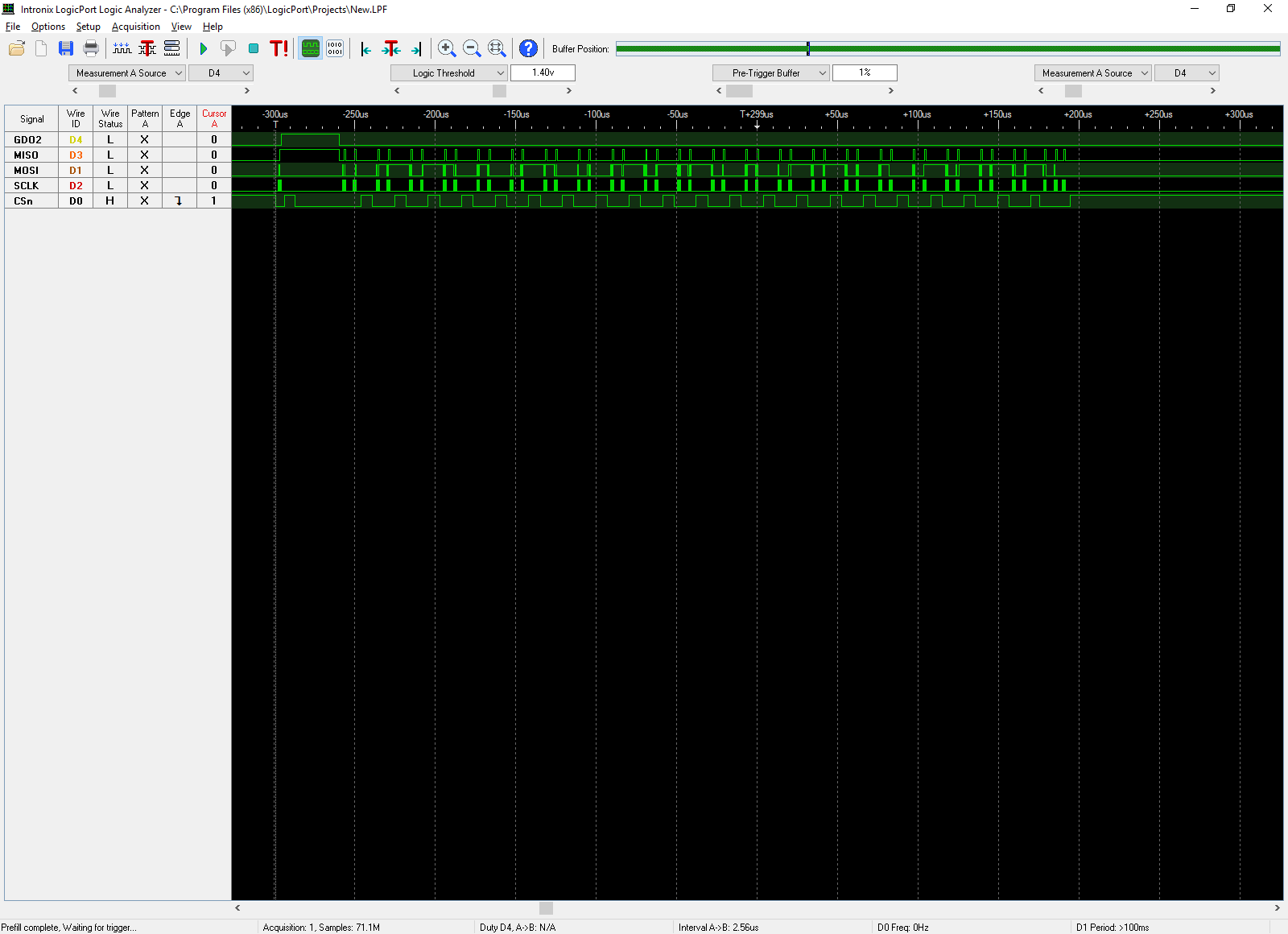
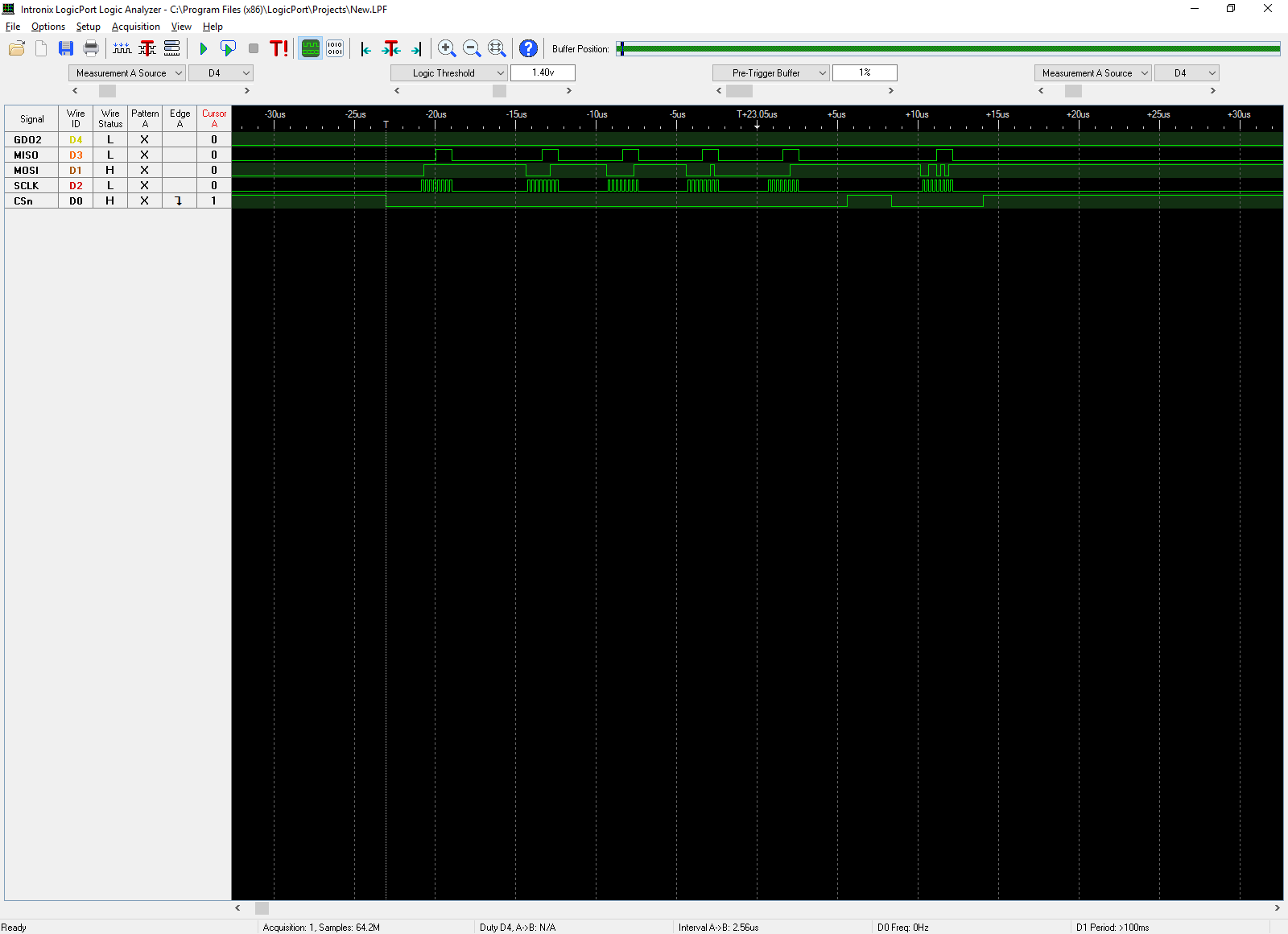
The CC110L is in receive packet mode.... first time packet is received a "spurious" byte appears before the length byte. This "extra" byte appears to be the CRC_Status byte

of a previous transmission (it's always the same value). This never happens again until RX restart. CC110L is in IDLE state and RX FIFO has been purged before SRX command

is issued... ???

  • If you have flushed the FIFO before entering RX the FIFO is empty and it is not possible that there is something other than the length byte as the first byte in the FIFO (given that your radio is programmed for variable packet length mode).
    Please share your register settings and your receive function so that we can take a look at it.
    Doing a SFRX should only be necessary if you are have an RX FIFO overflow or if you for some other reason knows that you are not interested in the packet. Under normal operation you will typically read out the complete packet + the status byte each time you receive a packet, hence the FIFO will be empty and no flushing is necessary. Please note that the FIFO should NEVER be flushed unless you are in some overflow state or in IDLE.
  • I am using the settings from Smart RF, and a register dump shows all is OK. I am temporarily using a TI 433MHz EVB module to eliminate any RF/hardware issues. I have trapped the output from the burst command byte by byte, and the first byte (after system reset) is always HEX $0E... (coincidence led me to believe it was the tail end of a previous packet)... next byte is $0D (correct packet length) and so on. All packets from here on are received correctly... i.e. first byte is always the packet length. I have no doubt that this is a software issue as I need to execute a SFRX before returning to RX..??

  • Please share your register settings and your code or pseudo code for how you init the radio and how you handle RX.
  • CC110L_.ZIP

    ;
    ;
    ;===============================;
    ;
    ; REGISTER SETTINGS FOR CC110L
    ; PACKET MODE... 433MHz,CHANNEL#0
    ;
    ; CC110L REGISTER ADDRESS
    ;
    REGADD	ADDWF	PCL		;ADD OFFSET TO PROGRAM COUNTER
    ;
    	RETLW	IOCFG0		;[00] CC110L ADDRESS... [02]
    	RETLW	FIFOTH		;[01] CC110L ADDRESS... [03]
    	RETLW	PKTCTRL0	;[02] CC110L ADDRESS... [08]
    	RETLW	FSCTRL1		;[03] CC110L ADDRESS... [0B]
    	RETLW	FREQ2		;[04] CC110L ADDRESS... [0D]
    	RETLW	FREQ1		;[05] CC110L ADDRESS... [0E]
    	RETLW	FREQ0		;[06] CC110L ADDRESS... [0F]
    	RETLW	MDMCFG4		;[07] CC110L ADDRESS... [10]
    	RETLW	MDMCFG3		;[08] CC110L ADDRESS... [11]
    	RETLW	MDMCFG2		;[09] CC110L ADDRESS... [12]
    	RETLW	DEVIATN		;[10] CC110L ADDRESS... [15]
    	RETLW	MCSM0		;[11] CC110L ADDRESS... [18]
    	RETLW	FOCCFG		;[12] CC110L ADDRESS... [19]
    	RETLW	RESRVD1		;[13] CC110L ADDRESS... [20]
    	RETLW	RESRVD2		;[14] CC110L ADDRESS... [29]
    	RETLW	RESRVD3		;[15] CC110L ADDRESS... [2A]
    	RETLW	RESRVD4		;[16] CC110L ADDRESS... [2B]
    	RETLW	TEST2		;[17] CC110L ADDRESS... [2C]
    	RETLW	TEST1		;[18] CC110L ADDRESS... [2D]
    	RETLW	TEST0		;[19] CC110L ADDRESS... [2E]
    	RETLW	FSCAL3		;[20] CC110L ADDRESS... [23]
    	RETLW	FSCAL2		;[21] CC110L ADDRESS... [24]
    	RETLW	FSCAL1		;[22] CC110L ADDRESS... [25]
    	RETLW	FSCAL0		;[23] CC110L ADDRESS... [26]
    ;
    ;
    ;===============================;
    ;
    ;
    ;

    Not quite sure what files you have received.. ?? I have attached the main software file. This is an update to a legacy product that used a "transmit only" communication link. This is being changed to a TX/RX and ultimately to a "nest" protocol. It is not possible to change the hardware/software at this stage. The software is written in assembler for a Microchip PIC uController. The main file handler for the TI device is in the CC110L.inc library file.The CC110L settings are all taken from SmartRF Studio for 433MHz 2400 Baud, Channel #0, GFSK, 0dbm. Further investigation of the problem indicates that the "spurious" byte is always the packet length +1, verified by sending various packet lengths. All software is functional with the exception of the  RXFIFO read routine. the 0xFF (RXFIFO read command) seems to be accepted OK (the command "send" routine is used for all commands with no problem... the software then falls through to the RXFIFO upload... the software retrieves the first byte as the packet length, adjusts for the two appended bytes and clocks the packet out. First time check fails because of the "extra" byte, and the second frame is received correctly. There is still something wrong, however, because the FIFO read does not return to the IDLE state (a full register dump shows that all register settings are as per SmartRF). The next attempt to address the device finds the SO line stuck high..!!! it is necessary to issue either a SFRX or a SIDLE command to free things up... ???  

  • Not an expert on assembly code so I have instead made a very simple example that shows you how the radio should be operated:

    I have used recommended settings from SmartRF Studio:

    #define PA_TABLE {0x60,0x00}
    
    static const registerSetting_t preferredSettings[]= 
    {
      {CC110L_IOCFG0,           0x06},
      {CC110L_FIFOTHR,          0x47},
      {CC110L_PKTCTRL0,         0x05},
      {CC110L_FSCTRL1,          0x06},
      {CC110L_FREQ2,            0x10},
      {CC110L_FREQ1,            0xA7},
      {CC110L_FREQ0,            0x62},
      {CC110L_MDMCFG4,          0xF6},
      {CC110L_MDMCFG3,          0x83},
      {CC110L_MDMCFG2,          0x13},
      {CC110l_DEVIATN,          0x15},
      {CC110L_MCSM0,            0x18},
      {CC110L_FOCCFG,           0x16},
      {CC110L_RESERVED_0X20,    0xFB},
      {CC110L_FSCAL3,           0xE9},
      {CC110L_FSCAL2,           0x2A},
      {CC110L_FSCAL1,           0x00},
      {CC110L_FSCAL0,           0x1F},
      {CC110L_TEST2,            0x81},
      {CC110L_TEST1,            0x35},
      {CC110L_TEST0,            0x09},
    };
    

    Common code for RX and TX:

    - Init MCU

    - Enable interrupt on falling edge of GDO0 (packet sent/received)

    - Strobe SRES

    - Configure radio with registers from preferredSettings

    - Write to PA_TABLE

    On the SPI this will look like this:

    TX Specific code:

    while(1)
    {
        Wait for button push
        Write packet to TX FIFO (0x03, 0x01, 0x02, 0x03)
        Strobe STX
        Wait for packet to be sent (interrupt on GDO0)
    }
    

    0x7F: Burst access to TXFIFO

    0x03: Length byte

    0x01, 0x02, 0x03: Payload

    0x35: STX

    RX Specific code:

    while(1)
    {
        Strobe SRX
        Wait for falling edge interrupt on GDO0
        Read RXBYTES register
        Read as many bytes from the RX FIFO as indicated by the RXBYTES register
    }


    0xFB: Read register RXBYTES (0x3B) – 0x06 is returned on MISO

    0xFF: Burst access to RXFIFO

    0x03, 0x01, 0x02, 0x03: Length byte and payload read from RXFIFO

    0xDB, 0xA0: status bytes

    I was running this code and all SPI plots showed the expected results (no extra bytes). Please try to do something similar and post a plot of where you are reading the unwanted byte.

    Siri


  • Thanks Siri...

    I'll dig through this and get back to you.... 

  • Your explanation was most helpful, particularly the use of RXBYTES to get the packet length. In coding this up I found the "bug" that was locking out the CC110L. I put your simple "packet" into Studio7 (03 01 02 03) and when I sent it and looked at RXBYTES it returned 07...!! and the packet was 04 03 01 02 03 XX XX.... It turns out that Studio7 (I was using the "expert" mode) counts the data packet and inserts the packet length itself.... I should have twigged this earlier... as the "extra" byte was always the packet length +1... !!! so mystery solved...

    One further thing you might help me with. I will need to be able to communicate with legacy devices using OOK. This mode is not explained very well in the CC110L data sheet... is there any better documentation available on using this mode ??

    Many Thanks


  • For OOK refer to this app note: www.ti.com/.../swra215e.pdf

    If there are follow-up questions regarding OOK I suggest you start a new thread.