This thread has been locked.

If you have a related question, please click the "Ask a related question" button in the top right corner. The newly created question will be automatically linked to this question.

Compiler/CC1310: I2C Slave Problem

Part Number: CC1310
Other Parts Discussed in Thread: TCA9617B, TCA9406, TCA9800

Tool/software: TI C/C++ Compiler

I developed with CC1310 as an I2C Slave.
This successfully communicates with CC1310 Master, Artik Master, and Renesas Master.
However, the target board(customer's board)does not normally communicate.
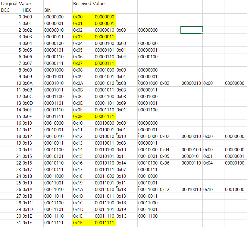
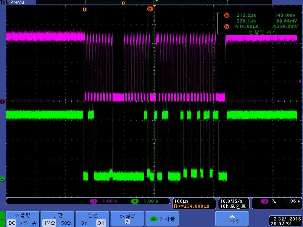
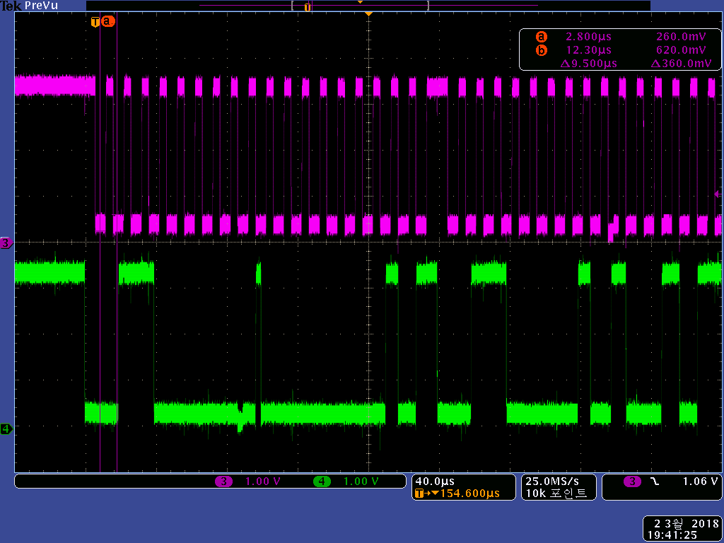
Symptoms are as follows: High level changes to Low level.
For example, when sending 0xC8, it receives 0x88, 0x80, etc. (confirmed by Slave).
Do you know any of these issues?

  • Hi,

    Do I understand it correctly that you are working with CC1310 implementing a I2C slave.
    The I2C slave can communicate with another CC1310 master, Artik master or Renesas master but when connected to a
    custom board the communication breaks down?

    If this is the case, what is the target master, another CC1310? Are you able to connect a logic analyzer and sniff the I2C lines?
  • Hi,

    Thanks for reply.

    Yes, you understand correctly.

    My target board is ALTERA(?). It works with linux.

    It is success case. slave address: 0x30, register address: 0x01, value: 0x96

    It is failure case. Slave address NACK.

    The waveform looks fine.

    It was confirmed through slave debugging that the received value was broken.

    I think the slave address nack also happens because the value is broken.

    There seems to be no problem on the waveform, but it seems to be different in the MCU. Could it be?

  • Hi,

    Thanks for the screen dumps, as you say, there seems to be no obvious problem in the waveforms.
    I understand it as the top one is when the CC1310 Slave is interfaced with any of the working MCUs and that the other two are when it is interfaced with the Altera, is this correct?

    For the screens related to the CC1310 <-> Altera setup, could you add in what data the slave actually receives (i.e. make it clear what you mean by broken)?
  • Hi,

    CC1310(Slave) - CC1310(Master) (OK)

    CC1310(Slave) - ARTIK(Master) (OK)

    CC1310(Slave) - RENESAS(Master) (OK)

    CC1310(Slave) - ALTERA(Master) (NG)

    The screenshots are CC1310 - ALTERA.

    I'm using function ti_lib_i2c_slave_data_get(I2C0_BASE);

    This is an example of data broken.

    When I send "0x05" from altera(master), cc1310(slave) receive "0x05" or "0x01".

    Sometimes, some high bit change to low bit.

    Last bit is not change. Bits connected last bit are not change.

    In the case of two or more connected bits, only the last bit is changed.

    Thank you.

  • Thanks for clearing that up for me.

    It is hard to say what might be the problem, but based on the fact that it works with the other MCUs I would assume it is related to the Altera I2C bus itself.

    You should check for differences between the platforms such as difference in pull-up resistor values and how these are implemented to try figure out what the two hosts do differently. Do you have any screenshots of the CC1310 slave interfacing with any of the working MCUs?
  • They say there is no problem communicating with their masters and other I2C slaves.

    There seems to be a difference the clock period and low level.

    ARTIK

    CC1310(Master) It is divided into two.

    No Renesas screenshots, sorry.

  • Hi,

    I'm starting to run out of ideas I'm afraid. You could give an extra check on the master to look on things like clock stretching.

    Looking at the CC1310 master scope and the Altera master scope, the clock signal does seem a bit difference (like you noticed as well). Seems like in the working MCU cases, the pow period is a bit longer then the high period.

    Maybe what you are seeing is the the device ending up in some corner case with the Altera implementation due to some difference in clock timings? It would have been helpful if you were able to run an actually logic analyzer on this and compare the analyzer data to what the slave receives.
  • Hi,

    Doe it affect that the low period is a bit longer than the high period?
    I have tried to test with CC1310(Master) at a faster cycle (from 100 kHz to 105 kHz), but the communication is no problem.

    The above waveforms are taken at the cable connector between the master and slave.
    Since the input signals from the slaves enter MCU directly, they may not be changed.

    At first, I suspected a low-level problem.
    However, judging from the test results, it seems to be a matter of timing.
    What do I doubt? Slave code? Master Code? Hardware?

    The customer does not modify the code of the master.
    Because it looks like there is no problem with the waveform, and the slave address NACK occurs
    They say it is a slave issue.

    I want to solve this problem quickly.

    Thank you very much.
  • Hi,

    It should not really matter. The slave would clock the data on the rising edge of the clock so as long it aligns with the data it should be fine.

    At this case, I would maybe doubt the hardware itself. I noticed now that it does not seem that the signal actually gets pulled to GND in the Altera case. I assume the small (3) and (4) symbols in the edge of the scope mark the GND level of the signal (seems to align with the assumption that the devices run at 3.3V).

    I noticed that in all the working cases, the signal goes to near GND, while in the ALtera case they seem to stop at ~0.5-0.6V. This is quite close to the limit of what is to be consider a safe logic zero (0.2 * Vdd). The pull ups on the i2c bus I assume comes from the Altera, if that is the case, can you figure out the value of them?
  • Hi,

    I also doubt about the low level.
    However, as the high level changes its value, the question is again.

    Altera has a level translator(TI TCA9617B). It makes the low level value to 0.6~0.8V.
    In fact, my board also has a level translator(TI TCA9406).
    There seems to be a problem with the specification of the two chips.
    So the recent I2C related developments are to be TI CC1310 Launchpad.

    In a recent test, Altera's level translator was switched to TI TCA9800. The result is a low level value change to 0.38~ 0.58V.
    As far as I know CC1310 Launchpad's VIL is 0.66V(0.2*Vdds).
    If so, the conditions are satisfied, but the results remain the same.

    As I know, the pull-up resistance value of Altera is 2.2kohm.
    And now I am testing it by switching to 10kohm.

    Thank you.
  • Hi,

    This seem to be a hard nut to crack. Do I understand you correctly that you moved to testing Altera -> Launchpad, and that this included one single TCA9800 level shifter?

    Let me know the results after switching the pull-up resistance!
  • Hi,

    Altera(TCA9617B, 2.2k/10k) - My Board(TCA9406) (NG)
    Altera(TCA9617B, 10k) - Launchpad (NG)
    Altera(TCA9800, 10k) - Launchpad (NG)
    Altera(TCA9800, 10k) - My Board(TCA9406) (NG)

    That's what I tested.
  • I'm afraid I don't have any more ideas on how to solve this. You could try bumping the supply to the launchpad to 3.8V just to see if this makes a difference, should give you more headroom on the low-level signals.
  • Hi,

    Where you able to reach any solution or conclusion regarding your problem?
  • I will mark this thread as "Think resolved" due to inactivity, feel free to re-open it if you have any more findings (or start another thread referring to this one).

    Note that a solution was not found.